


DBl-ThE
N
LATCH
signat
for
the
lst
LO
phase
tock
is sent
on
this
line.
DB2-Reserved
for
future
apptications.
DB3-This
lin€ resets
the
buffer
sequencer
at
the
outsEt
of
a
talk
cycle
for
the counters.
DB4-This
tine (CONTROL
LATCH)
tatches
a conrrot
word
into
the
output
buffers
ot
VZOZS
on
the
Error
Amplifier
board.
DBS-This
signal
clears
all
the
counter
stages
in
the
counter-
buffer
circuits
in
preparation
,or
a
count
sequence.
DB6-This
line
tatches
the
N
data
in
Ul022.
DB7-This
line
is
used
as
a
clock
to step
data
into
U1422
and
U304gA,
and
for
the
data
sent
in
the
1st
LO
phase
tock.
R3012
and
G2010
act
as
a
delay
to
provjde
adequate
setup
tim€
for
the
data
prior
to
the
clock
signal
arriving.
Buffers
U3094,
UgOgO,
and
U2026
are
the
tatk
buffers
that
send
data
to
the
microcornputer.
UgOl
g
and
-U2030A
make
up
a step-enabler
that
enables
the
talk
bufrers
one
at
a
time when
requested
by
the
micro-
computer.
Input
Ampliflers
and
Multiptexer
,
Q1018
brings
the
-5
dBm,
16
MHz
to 20
MHz
signal
f.r9T-tl9
2nd
LO
up
to
TTL
tevets.
U2010
divides
the
16-20
MHz
by
32 and
256
before
it sends
it
to mutti-
plexer
Ul018.
U2056
amptifies
the
_50
dBm, 10
MHz
lF.
L2056
anct
C2056
act
as
a
10
MHz
bandpass
fitter
on
th€ input
of
u2056.
R3056 provides
current
to
the
open_
collector
output
of
U2056.
C3OS2
couples
the
!!^UHz
signat
into
U4056.
U4056
acts
as a
dlvide-by-
128
counter.
The
signat
then
goes
to
U101g.
All-oth€r
input
signals
are
at
TTL
levels
and
are
con-
nected
direcfly
to
U101g.
The
ouput
of
U3010A
is
con_
nected
to
U1018
so
that
the clock
can
be counted
for
diagnostic purposes.
UlO1g
selects
one
of
its
inputs
according
to
the
data
in
U1022.
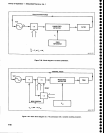
+2n
Counter
The
output
of
U1019
goes
into
a
series
of
dividers
made
up
of
U1050
and
U2050A.
Various
outputs
of
these
dividers ar€
connected
to
multiplexer
Ul046
to
give
a
+2n
counterwhere
n
-
1,2,
a,6,
g,
i0,11,
ori2
(n
is sel€cted
by
the
data
stored
in
U1022).
A
strobe
input
to
U1046
disables
the
multiplexer
when pulled
high.
Theory
of
Operation
-
4g4A/4g4Ap
SeMce,
Vol.
1
21-Bit
Counter
The
21-bit
counter
counts
the
1OO
MHz
reference
frequency
to
give
a mgasursrnent
of
the
time
required
to complete
a
given
number
of
cycles
of
the selected
input
signal.
The
counter
itself
consists
of
UlGlg,
U2018,
U1028,
and
U2034.
Ul0gg
is
an
ECL
divider.
Q1034 and
Q1044
are
ECL-Io-TTL
translators
for
the
+2
and
+4,
respectively.
The
+4
go€s
to
U20lg
where
it
is
countgd
with
TTL
dividers.
and
the
divider
chain
contin_
ues
through
U2034.
The
output
of
each
stage
goes
to
an
output
buffer
so
the
rnicrocomputer
can
read
th€
final
number
of counts.
Therefore,
the microcomputer
measures
the
time
period
during
which
the
counter
was
enabfed.
The
counter
is
€nabted
by
U20508
and
rJ2046
for
a
^time
period
equal
to eight
cycles
of
the
output
of
the
+2n
counter.
At
the start
of a
count,
the
microcomputer
selects
the
input
signal
to
be counted
and
sets
ttre
'n'
number
for
thE
-r2n
counter.
The
COUNT/RESET
tine
is
then
pulled
high
to
reset
alt
of
the
countErs.
U2046A
is
preset
with
Q
in
the high
$tate,
which
disables
the
21_bit
counter.
The
COUNT/RESET
tine
then
goes
high
to
start
th€
measur€ment
process,
Th€
output
of
U1046
goes
to
U20508
where
it is
further
divided
down.
On
the first
rising
edge
at
pin
11 of
U20508,
Q
of
u2046A
goes
low
to start
the 21-bit
counter.
on
the eighth
count
of
u20508,
u2046A
steps
back
to its
original
state,
which
stops
the
21-bit counter.
At
the same
tirne,
U20468
pulls
the strobe
to
the
+2n
counter
high
to
stop
any
further
counts
in
U20508.
The
microcomputer
can
now
read
the VALID
COUNT
line
to
determine
when
the
count procEss
is completEd,
and
then read
the
data
that
is
stored
in
the 21-bit
counter.
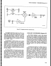
PHASE
LOCK
SYNTHESIZER
(Diagrams
39
and
40)
The Phase
Lock
Synthesizer provides
frequency
control
and
stability
for
the
lst
local
oscillator.
The cir-
cuit
consists
of
the
Synthesizer
and
phase
Lock cir-
cuits.
The
Phase
Lock
assembly
includes
the Error
Amplifier,
Offset
Mixer,
Controll€d
Oscillator,
and
Strobe Driver.
The
Phase
Gate
Detector
(shown
on
diagam
36) is also
part
of
the
phase
lock ciruitry.
Synthesizer
(Diagram
39)
The
Synthesizer
uses
the
100
MHz reference
fre-
quency
from
the 3rd
Converter
to
generate
the
25 MHz
reference
frequency
for
the
Offset
Mixer and
the
+N
fre-
quency
(determined
by
the N
number
from
the
proces-
sor)
for
the
phase/frequency
detector in
the
Offset
Mixer.
The
+N
frequency
is within
the 32 kHz
to 94 kHz
range.
7-83