


o
I
)
o
o
o
o
o
a
I
o
o
I
o
t
I
t
a
I
o
o
o
o
o
I
O
o
o
o
I
o
o
t
o
a
t
I
I
a
o
o
t
I
o
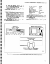
Performance
Check
procedure
-
4g4Al4g4Ap
Servlce
Vol.
1
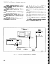
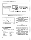
b.
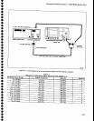
Connect
the
test
eguipment
as
shown
in
Figure
4-15.
Set
the
Spectrum
Anatyzer
controls
as
followj:
l.
Establish
a
reference
setting
for
the first
10
dB
increment
by
pressing
dB[Ref
on
tie
po*"i
meter.
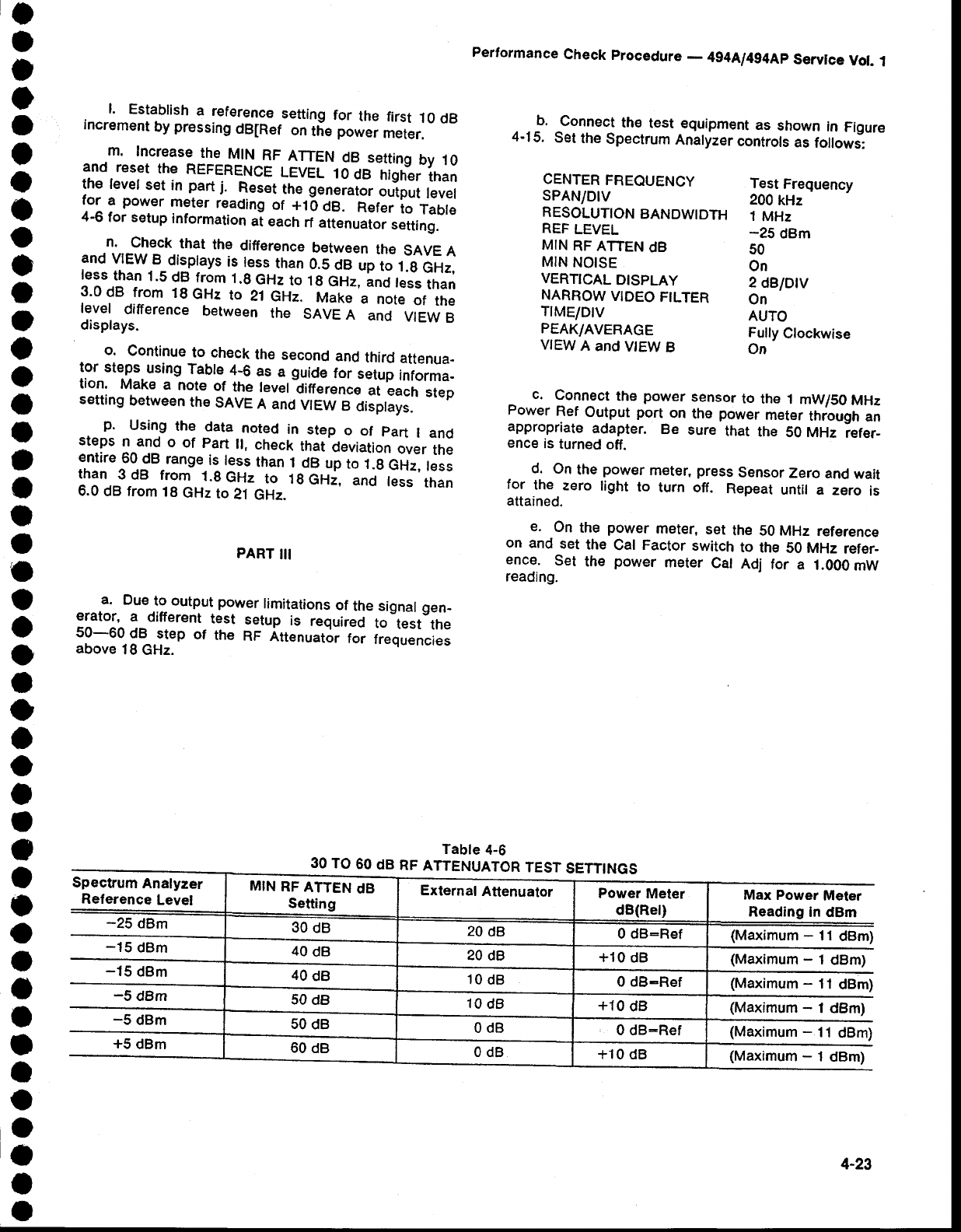
m.
Increase
the
tr4tN
RF
ATTEN
dB
setting
by
10
and
reset
the
REFERENCE
LEVEL
10
dB
higher
than
the levet
set
in
part j.
Reset
tn"
!"n"i"i*
output
level
for
a
power
meter
reading
of
+16
Oe.
Eeter
to
Tabte
4-6
for setup
information
ai each
rf
attenuaior
setting.
n.
check
that
the
difference
between
the
SAVE
A
and
VIEW.B_displays
i9
t^e1
than
0.5
dB
up
to
.t.A
GHz,
less
than
1.5
dB
from
1.9
GHz
to f
g
Gftz,
lnd
tess
than
3.0
dB from
1g
GHz
to
21
GHz.
frrt"f."'"
'note
of
the
level
difference
between
the
SAVE
A
and
VIEW
B
displays.
o.
Continue
to cheek
the
second
and
third
attenua-
tor
steps
using
Table
4;6
as
a
guide
for
setup
informa-
tion.
Make
a
note
of
the
level
liference
at
each
step
setting
between
the
SAVE
A and
VIEW
B
ctisptays.
p.
Using
the
data
noted
in
step
o
of
part
I and
steps
n and
o
of
part
lt,
check
that
deviation
over
the
entire
60
dB
range
is
less
than
I
dB
up
to
1.g
GHz,
teis
than
3dB
from
1.gGHz
to
lgGH;,
and
tess
than
6.0
dB from
1B
GHz
to
21
GHz.
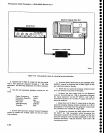
PART
III
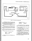
.a.
Due
to-
output
power
limitations
of
the signal
gen-
erator,
a
different
test
setup
is
required
to
test
the
50-60
dB
step
of
the
RF
Att€nuator
foi
frequencies
above
18
GHz.
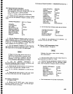
CENTER
FREQUENCY
SPAN/DlV
RESOLUTION
BANDWIDTH
REF
LEVEL
MIN
RF ATTEN
dB
MIN
NOISE
PEAK/AVERAGE
VIEW
A
and
V|EW
B
Test
Frequency
200
kHz
1
MHz
-25
dBm
50
On
Fully
Clockwise
On
VERTICAL
DISPLAY
21BIDIV
NARROW
VTDEO
FILTER
On
TIME/DIV
AUTO
^
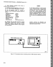
c.
!o1n_ect
the
power
sensor
to the
1 mW/50
MHz
Power
Ref
Output
port_on
the
power
meter
through
an
appropriate
adapter.
Be
sure
that
the
50 MHz
iefer-
ence
is
turned
off.
d.
On
the
power
meter, press
SensorZero
and
wait
for
the
zero
light
to
turn off.
Repeat
untit
a zero
is
attained.
e.
On
the
power
rneter,
set
the 50
MHz reference
on
and
set
the
Cal
Factor
switch
to
the
S0 MHz
refer-
ence.
Set
the
power
meter
Cal
Adj
for
a
1.000mW
reading.
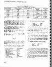
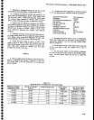
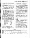
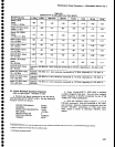
Table
4-6
30
TO
60
dB
RF
ATTENUATOR
TEST
SETTINGS
Spectrum
Analyzer
Reference
Level
-25
dBm
-15
dBm
-
-15
dBm
-5
dBm
MIN
RF
ATTEN
dB
Setting
External
Attenuator
Power
Meter
dB(Rel)
Max Power
Meter
Reading
In
dBm
30
dB
20
dB
0 dB-Ref
(Maximum
-
11
dBm)
40
dB
20
dB
+10
dB
(Maximum
-
1
dBm)
40
dB
10
dB
0 dB-Ref
(Maximum
-
11
dBm)
50
d8
10
dB
+10
dB (Maximum
-
1
dBm)
-5
dBm
50
dB
0dB
0 dB:Ref
(Maximum
-
11
dBm
+5
dBm
60
dB
0dB
+10 dB
(Maximum
-
1
dBm)
4-23