


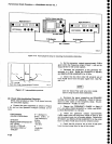
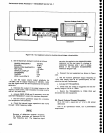
Performance
Check
procedure
-
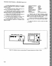
4g4A/4g4Ap
Service
Vol. l
Speclnm Andyrcr
Undcr Tcst
Iodrl.l.d RF
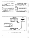
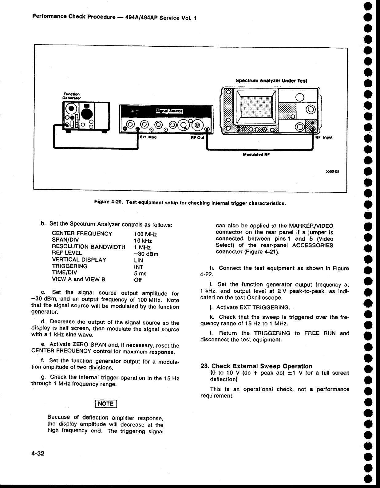
Figure
4'20.
Test
equlpment
selup for
checking Intemal
trlgger characteri3tica.
o
a
o
o
a
o
I
a
o
t
t
e
o
a
o
o
o
a
f
o
t
o
a
o
o
O
o
o
o
a
a
o
o
a
a
o
o
a
o
a
c
o
o
a
4-32
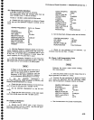
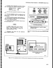
b.
Set
the Spectrum
Analyzer
controls
as
follows:
CENTER
FREQUENCY
100
MHz
SPAN/DIV
10
kHz
RESOLUTTON
BANDWTDTH
1
MHz
REF LEVEL
-30
dBm
VERTICAL
DISPLAY
LIN
TRIGGERING
INT
TIME/OIV
S ms
VIEW
A and
V|EW
B
Off
_
c.
Set the
signal
source
output
amplitude
for
-30
dBm, and an
output
frequency
of 100
MHz.
Note
that
the signal source
will
be
modulated
by
the function
9enerator.
d.
Decrease
the
output
of
the signal
source
so
the
display
is
half screent
then rnodulate
the signal
source
with
a 1 kHz
sine
wave.
e.
Activate
ZERO
SPAN and,
if
necessary,
reset
the
CENTER FREQUENCY
control
for
maximum
response.
f.
Set
the
function
generator
output
for
a
modula_
tion amplitude
of
two
divisions.
g.
Check th€
internal
trigger
operation
in
the 15 Hz
through
1
MHz
frequency
range.
Because
of
deflection
amplifier
response,
the
display amplitude
will
decrease
at
the
high
frequency
end.
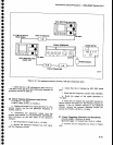
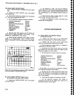
The
triggering
signal
can also
be applied
to
the MARKER/VIDEO
connector
on
the rear
panel
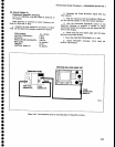
if a
jumper
is
connected
between
pins
1 and
5
(Video
Select)
of
the r€ar-panel ACCESSORIES
connector (Figure
4-21).
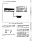
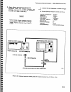
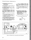
h.
Connect the
test equipment
as shown in Figure
4-22.
i.
Set the
function
generator
output
frequency
at
1 kHz,
and output
level at 2 V
peak-to-peak,
as indi-
cated on
th€ test Oscilloscope.
j.
Activate EXT TRIGGER|NG.
k.
Check that
the
sweep is
triggered
over
the
fre-
quency
range ot 15 Hz
to
1 MHz.
I.
REIUTN
thE TRIGGERING
tO FREE
RUN
ANd
disconnect
the
test equipment.
28.
Check External Sweep
Operation
{O
to t0 V
(dc
+
peak
ac) *1 V for a lull screen
deftection)
This is an operational check,
not
a
performance
requirement.