


o
o
o
o
o
o
o
o
o
o
o
o
o
o
o
O
o
o
o
o
o
o
o
a
o
o
o
o
o
o
a
o
O
o
o
o
o
o
o
o
o
o
o
o
_
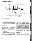
The
2GHz
Limit€r
(A10)
operates
from
100
kHz
to
2
GHz.
lt
has
a
linear
two-port
transfer
characteristic
of
unity
(-1
dB)
until
the
input
exceeds
+5
dBm.
Above
this
point,
the
internai
detEctor
OioOes
conduct,
reflecting
part
of
the
RF
input
energy
back
to
the
source..
A:
lhe
input
level
rises,
the-Limiter
reflects
more
signal,.limiting
the
amount
that
can pass
through
the
mixer,
thus
protecting
the
mixer
from
being
over_
driven.
The
1.gGHz
Low-pass
Fitter (FL10)
strips
the
incoming
signal
of
any
frequen"y
cbmpon"nts
above
1.9 911.
and
passes
dtt
treiueniy
"olnion"nt.
o"ro*
1.8
GHz
to
Fitter
Setector
swiicn
Si2.
The
presetector
(FL12)
is
a
1.7-1g
GHz
yttrium_
lron-Garnet
(ylG)
filter
that
provides
nigh
setectivity
anO
y1S"-jl"qyency
rejection.
Tuning
c-urrent,
which
is
near
500 mA
at
21
GHz,
is
provideJ
by
the
preselector
Driver
(A42)
circuits.
The
presele"ior
op"rates
on
bands
2,
g,
4,
and
S.
Because
the
preselector
is
sensi-
tive
to output
toad
impedance,
a
g
dB
Attenuator
(AT11)
is
inserted
between
the
pr€s€lector
output
and
one
port
of
the Fitter
Select
switch
to hetp
isotate
output
loading.
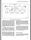
1st
Mixer
The
1st
Mixer
{A12)
circuit
consists
of
a
single
bal_
anced
mixer,
a coupler,
and
a
g0o
phase
shifter.
A
bal-
anced
mixer
inherently
has
less
conversion
loss
com_
Par€d
to an
unbalanced
mixer,
and
local
oscillator
feedthrough
to
ths
RF
port
is
minimized.
The
locat
oscillator
input
is
split
through
a
broad-band
multi-
section
coupler
whose
outpute
are
equal
in
power
but
9p
deoqegs.
out
of
phase.
an
aOOiitonat
tiO
degree
phase
shift
is
cascaded
with
the
appropriate
signal
to
create
a
180
degree
phase
difference
ttrat
is
ipptied
across
a
pair
of
series-connected
Schottky
diodes.
The
result
is
that
the
diodes
are
alternatety
switcned
on
and
off
as
the local
oscillator
cycles.
The
node
between
the
two
diodes
is
isotated
from
11"-,,1^"j !O ^ilpu.
by about
O0
dB so
the
RF
input
is
apptteo
to
this
node.
The
blocking
capacitor
at
the
input
connector
permits
broadband
signal
application
from
the
RF
port,
while
blocking
the
dc'diode
bias
from
g.etting.
to
the
RF port
and
the
ipectrum
analyzer
input.
Mixer
bias is
supplied
from
the
ist
LO
Driver
board
via
the
829
MHz
lF
circuits,
4.5
GHz
Filter,
Diplexet,
Direc_
tional
Filter,
and
Transfer
Switch.
Bias
return
is
through
assembly
A1
1
to
ground.
Excluding
losses
in
the
lF
filtering
circuitry,
the fun_
dam€ntal
conversion
loss
of
ths
l st
-Conuener
is about
14
dB, and
the
third
harmonic
conversion
loss
is
about
24.d8.
The.
Schottky
diodes
are
mounted
in
a
mixer
suo-assembty
(A12A1)
so
that
they
can
be
easily
replaced.
Theory
of
Operation
-
4g4Al4g4Ap
Servtce,
Vot
l
1st Local
Oscillator
The
lst
LO
(A16)
is
a
ytG
(yttrium-tron-Gamet)
oscillator
that has
a
tuning range
of
2.072
to
6.4
GHz.
The
oscillator
assembly
includes
the
interface
circuit
board
that
couples
operating
and
tuning
voltages
from
the
l.st
LO
Driver,
Span
Attenuator,
and
Error
Amptifier
circuits
to
the oscillator.
The
+15
Vl
voltage
provides
operating
bias
for
the
p,l"jl1!or.-
The_
suppty
is
protected
and
iecoupted
by
VRl
010,
Cl
0t
6, and
L1
01
1.
Th: s9c9nd
suppty,
+t
S
t2:
is
not
used
in
this instrument.
VRlolg
anct
VR1019
clamp
transient
voltages
from
the
tune
voltage
coil.
lt
atso protects
the driving
circuits
from
the
transients
induced
when
degaussing.
When
the
FM
coil is
used
to
sweep
the osciilator,
relay
K101S
closes
and
couptes
C1d12
and
C1014
across
the
tune coil,
The
capacitors
tower
the
noise
bandwidth
of
the main
coil
driving
circuit
while
the
FM
coil
is in
operation.
The
heater provides
temperature
stability.
Power
Divider
The
Power
Divider (A13)
splits
the
output
of
the 1st
LO
(YlG
osciilator)
to isolate
the 1st
Mixei
from
thg
tst
!O
OUjP,qT
.front-panet
connector.
Basicaily,
the
Power
Divider
is
two multi-section
directional
couplers
that
are
cascaded
to
produce
two
ports
having
equal
power.
The
isolation
between
output
ports
is 15
dg or
mors at
the op€rating
frequency.
The
power
Divider
also
provides
an improved
load
to
the local
oscillator.
Transfer
Switch
The
Transfer
Switch
(S13)
is
a
three-port coaxial
relay
that
selects
1st
lF
signals
from
either
the
1st
Mixer
or
from
the EXTERNAL
MIXER
input.
This
allows
the
use of an
external
mixer
by by-passing
the
lst
Con-
verter
circuitry.
The function
is
controlled
by
circuitry
on
the
RF Interface
board.
lt is
autornatically
actuated
when
waveguide
bands
ars
selected
or
the
front-panel
EXT
MIXER
push
button
is
pressed.
ln
Option
07 and
08 instruments,
the
external
mixer
capability
is
detet€d.
In
those
instruments,
W125
directly
connects
the 1st
Mixer
output
to the
Directional
Filter.
In
Option
07 instruments,
the
transfer switch
selects
between
the
50O and
7SO
inputs
to feed
the
Step Attenuator.
7-5