


Performance
Check
Procedure
-
4g4A/4g4Ap
Servlce
Vol.
1
-
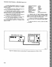
c. Set
tle_:rlveep
oscillator
controls
for
a
cw
output
frequency
of
500
MHz and
an
amptitude
of
+20
Oe;1V
at
the 75O INPUT.
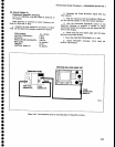
d.
lf
necessary,
set
th€
cAL
AMPL
adjustment
for
5
divisions on
the
Spectrum
Analyzer
display.
e. Reset
the sweep
oscillator
controls
lor
a
sweep
output from
0.01 GHz-l
GHz.
Enable
single
sweep
on
the sweep
oscillator,
and
activate
MAX
HOLD.
f. Make
a
note
of
the
highest
and
lowest peaks
for
later
comparison,
then
deactivate
MAX
HOLD.
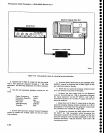
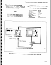
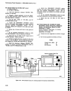
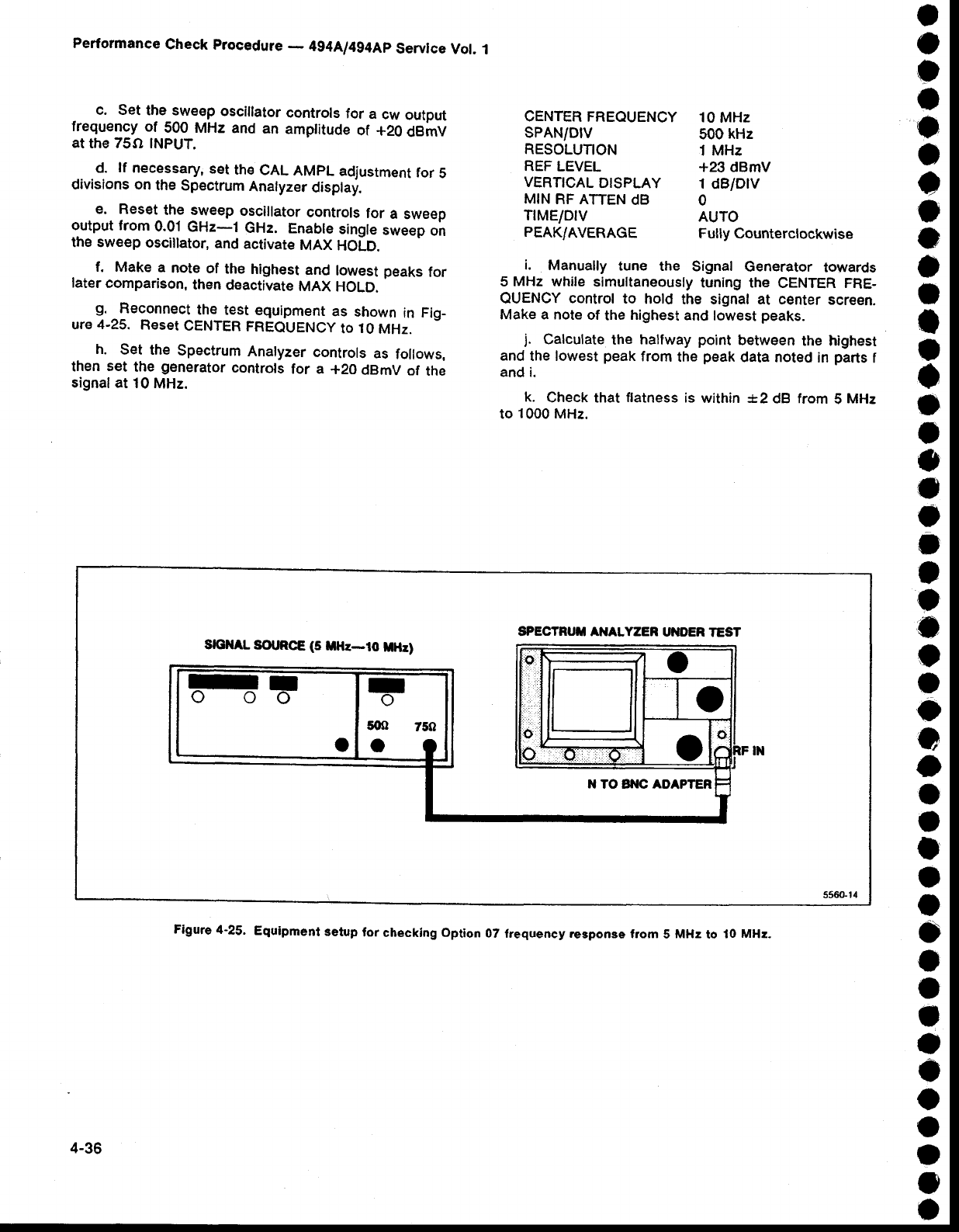
S,
Reconnect
the
test
equipment
as
shown
in
Fig-
ure
4-25.
Reset
CENTER
FREQUENCy
to
10
MHz.
h.
Set the
Spectrum
Analyzer
controls
as
follows,
then
set
the
generator
controls
for a
+20
dBmV
of
the
signal at
10
MHz.
CENTER
FREOUENCY
10
MHz
SPAN/DfV
500
kHz
RESOLUTION
1 MHz
REF
LEVEL
+23 dBmV
VERTTCAL
DTSPLAY
1
dBlDlV
MIN
RF ATTEN
dB
O
T|MEIDIV
AUTO
PEAK/AVERAGE
Fully
Counterclockwise
i.
Manually
tune the
Signal
Generator
towards
5
MHz while
simultaneously
tuning the
CENTER FRE-
QUENCY
control
to
hold
the signat at center
screen.
Make a note
of
the
highest
and
lowest
peaks.
j.
calculate
the
halfway
point
between
the highest
and
the lowest
peak
from
the
peak
data noted
in
parts
f
and i.
k.
Check that
flatness
is
within !2
dB from
5
MHz
to
1000
MHz.
SPECTRUT ANALYZER
UNOER
TEST
Srcl|AL
SOT RCE
(5
ltHz-io
tdHz]
E!-
F
Figure
4-25.
Equipment
setup
for
checklng option
07 frequency response
from
5
MHz
to
10
MHz-
4-36