TABLE
OF
CONTENTS
(Cont.)
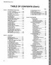
Page
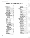
Section 7
THEORY
OF OPERATTON
(Cont)
DETAILED
DESCR|PT|ON
................
.....
7
-4
1ST
CONVERTER
SECTTON
.............
7_4
RF Interface
Qircuits
....................
7-4
'l
st
Converter
.................
..........,,,..
7-4
RF
Input
...............
7-4
Preselector
Circuits ...........,.....
74
lst
Mixer
..............
7_5
1st
Local
Oscillator
..................
7_5
power
Divider
......
7-s
Transfer
Switch
.... 7-s
Directional
Filter
................,......
Z-6
2O72MHz
tF
Fitters
....,............
7-6
Diplexer
and
Filter
...,...............
Z-6
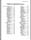
2ND
CONVERTER
SECTTON
............
7_7
2072
MHz 2ND
CONVERTER
.......
7-8
Four-Cavity
Fi|ter
.......... ...........
Z
-g
Mixer
Circuit
............................
7-g
Precision
External
Cables
........
7-9
Filter
to
Mixer
RF
Input
Gable
....................
7-10
2nd LO
to Mixer
LO
Input
Cable
....................
Z-10
2182MHz
PHASE
LocKED
2ND
LO
.....................7-10
2182MHz
Microstrip
Oscillator
.............
7-10
2200
MHz
Reference
Board
....................7-11
220O
MHz
Reference
Mixer .........
...........7-11
16-20
MHz
phaselock
Board
....................7-11
829
MHz 2ND
CONVERTER
.........7-19
lF
Section
............
7,13
829
MHz
Diplexer
.,..............
7-t
g
829
MHz
Amplifier
...............
t-13
829 MHz
2nd
Converter
...,..7-14
110
MHz lF
Se|ect...............
7-i5
LO
Section
...........
7-16
Phase
Lock
Circuit ..............
7-16
2nd
Local
Oscillator
Ouput Circuit
... 7-19
719
MHz
Output
Circuit
.......
7-18
3RD
CONVERTER
SECTION
......,.....
7-19
110
MHz tF
AMpLtFtER
...............
7-19
110
MHz
FILTERS
3rd
CONVERTER
............ ..............
7
-2A
100
MHz
Oscillator
..................
7_20
Mixer.........
...........
7_20
Distribution
Amplifier
...............
7
-20
Calibrator
.............2-21
REFERENCE
LOCK
......,...............
7-21
External
Referance
Det€ctor
...,...,,..,...7-21
Page
Frequency
Synchronizer ..........
7-21
Phase/Frequency
Detector
...,.,..,.....,7-21
Tune Amplifi
er
...............
........... 7-22
Lock Detector ..............
.........
"..
7
-22
rF
sEcTtoN ...................7-22
VAR|ABLE
RESOLUTION
............. 7-22
VR
fnput
...............7-22
1st Filter
Select .....7-22
100 Hz and 10 Hz
Bandpass
Filter
..........
.............. 7
-24
1st Mixer
,..,,.....7-25
Bandpass
Filter
..........
....,.,..
7
-25
2nd Mixer .........7-25
Local
Oscillator .............
......
7-26
10
dB Gain Steps ..........-..........7-26
20
dB Gain Steps .....................7-26
Band
Leveling
Circuit ........,...... 7-27
VR
Mother Boards ................... 7
-27
2nd
Filter
Select
....7-28
Post
VR Amplifier
Circuit
.........7-28
LOG
AMP
and
DETEGTOR
.......... 7-29
Log Amplifier Circuits .............. 7-29
Detector
Circuit
.-...7-31
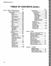
DTSPLAY
SECTTON
........7€3
FUNCTIONAL
DESCRIPTION ....... 7-33
VIDEO
AMPLIFIER .,,.7.33
Log Mode
Circuits
................... 7-33
Linear
Mode Circuits ..............-.
7-34
Pulse
Stretch Circuit
................ 7-34
ldentify
Circuit
.......
7-35
Digital
Control
Circuit ...............
7-35
vrDEo
pRocESSoR
.................... 7-35
Interface
with
1405 TV
Sideband
Adapter .............-...... 7-35
Mdeo Marker ...........................
7-36
Video
Leveling .......,...... ...........
7
-37
Video
Leveler
Circuits .............. 7€7
Video
Filter Circuits ......,..........
7-37
Video
Blanking
.-..............,........ 7-39
DIGITAL STORAGE
7-39
Verticaf
Section
.....740
Digitizing Circuits ................ 743
Address Decoding ............... 7-43
Interface
Logic ......... ..,........
743
Maximum
Hold .................... 743
Constant Circuit
..................
7-43
Output Circuits
....................
7-44
Peak/Average
Level
Circuits
.............7-44
Horizontal
Section
.....-.............
7-44
Marker lC
............................ 7-46
Tracking
Digital-to-
Analog
Converter ................
7*46
Update
Marker
Circuits
.......746
a
o
o
o
't
o
o
a
a
a
o
o
o
a
o
o
t
o
o
I
o
I
o
o
o
o
o
o
o
o
o
t
o
o
o
o
o
a
o
o
o
o
o
o
494A1494AP
Servlce
Vol.
1
vl


