


o
O
o
I
a
o
o
I
O
o
o
t
o
I
o
I
I
I
o
o
O
o
a
O
o
O
a
O
o
o
a
o
o
o
O
o
o
o
o
o
o
a
o
o
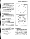
Malntenance
-
4g4A/4g4Ap
service
vot.
1
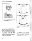
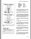
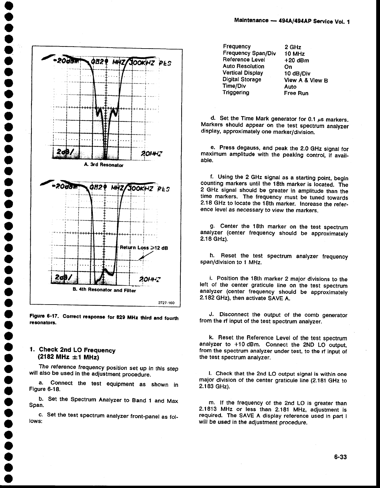
A
3rd
Resonator
Retu?n
Lo-ss
>12 dA
B.
4th
Resonator
and
Fllter
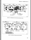
Figure
6-17.
Corect
re3ponse
tor
g29
MHr
tlrlrd
and
fourth
resonators.
d.
Set
the
Time
Mark
generator
for
0.1
Fs
markers.
Markers
should
appear
on
the
test
sp€ctrum
analyzer
display,
approximately
one
marker/division.
e.
Press
degauss,
and
peak
the 2.0
GHz
signal
for
maximum
amplitude
with
the
peaking
control,
if avail-
able.
f.
Using
the 2
GHz signal
as
a starting
point,
begln
counting
markers
until the
18th
marker
is located.
The
2
GHz signal
should
be
greater
in amptitude
than
the
time
markers.
The
frequency
must
be
tuned
towards
2.18
GHz
to locate
the 18th
marker.
Increase
the
refer-
ence
level
as necessary
to
view
the markers.
S.
Center
the 18th
marker
on
the
test
spectrum
analyzer
(center
frequency
should
be
approximately
2.18
GHz).
h.
Reset
the
test
spectrum
analyzer
frequency
span/division
to
1 MHz.
i.
Position
the
18th
marker
2 major
divisions
to
the
left
of
the
center
graticule
line
on
the test
spectrum
analyzer
(center
frequency
should
be
approximately
2.182
GHz),
then
activate
SAVE A.
J. Disconnect
the output
of
the
comb
generator
from
the
rf input
of
the test
spectrum analyzer.
k.
Reset the
Reference
Level of
the test
spectrum
analyzer
to
+10
dBm.
Connect
the
2ND
LO
output,
from
the
spectrum analyzer
under
test, to the
rf input of
the
test spectrum
analyzer.
l.
Check that
the 2nd
LO output signal
is
within one
major
division
of
the
center graticule
line
(2.181
GHz
to
2.183
GHz).
m.
lf
the frequency
of
the znd Lo is
greater
than
2.1813
MHz or less
than
2.181
MHz,
adjustment
is
required.
The
SAVE A
display
reference
used in
part
I
will
be
used in
the adjustment
procedure.
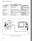
Frequency
Frequency
Span/Div
Reference
Level
Auto
Resolution
Vertical
Display
Digital
Storage
TimelDiv
Triggering
2GHz
10
MHz
+20
dBm
On
10
dB/Div
ViewA&ViewB
Auto
Free
Run
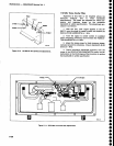
1.
Check
2nd
LO
Frequency
(2182
MHz
*i
MHz)
...
The reference
frequency
position
set
up in
this
step
will also
be
used
in
the
adiustrnent
procedure.
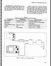
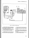
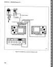
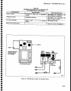
a.
Connect
the
test
equipment
as shown
in
Figure
6-18.
Set
the
Spectrum
Analyzer
to Band
1 and
Max
Set
the
test spectrum
analyzer
front-panel
as
fol-
b.
Span.
c,
lows:
6-33