


I
o
a
I
o
o
o
t
o
o
o
J
o
o
o
o
I
a
t
a
I
a
o
o
o
o
o
o
I
o
I
o
I
a
o
C
I
o
o
o
o
I
I
o
Section
2
-
494A1494Ap
Service,
Vol.
1
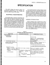
SPECIFICATION
This
section
includes
the eiectrical,
physical,
and
environmental
characteristics
of
this insirument.
Any
instrument
specification
changes
due
to options
ari
listed
in
the
Options
section
of
this
manual.
ELECTRICAL
CHARACTERI
STICS
-
The following
tables
of
electrical
characteristics
and
features
apply
to
the
spectrum
analyzer
after
a
3O_minute
warm
up
and
after
doing
the
front-panel
CAL adjust_
ments,
except
as
noted.
The
performance
Requirement
column
defines
some
characteristics
in
quantitative
terms
and
in limit
form.
The
Supplemental
lnformation
column
explains
performance
requirements
or
provides
perfor-
mance
information.
Statements
in
this column
are
not
considered
to
be
guaranteed
performance
and
are
not
ordinarily
supported
by a
performance
check
procedure.
P.rocedures
to verify
performance
requirements
are pro_
vided
in
the Performance
Check
portion
of
thrs
manual.
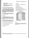
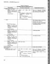
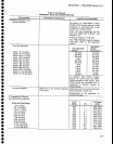
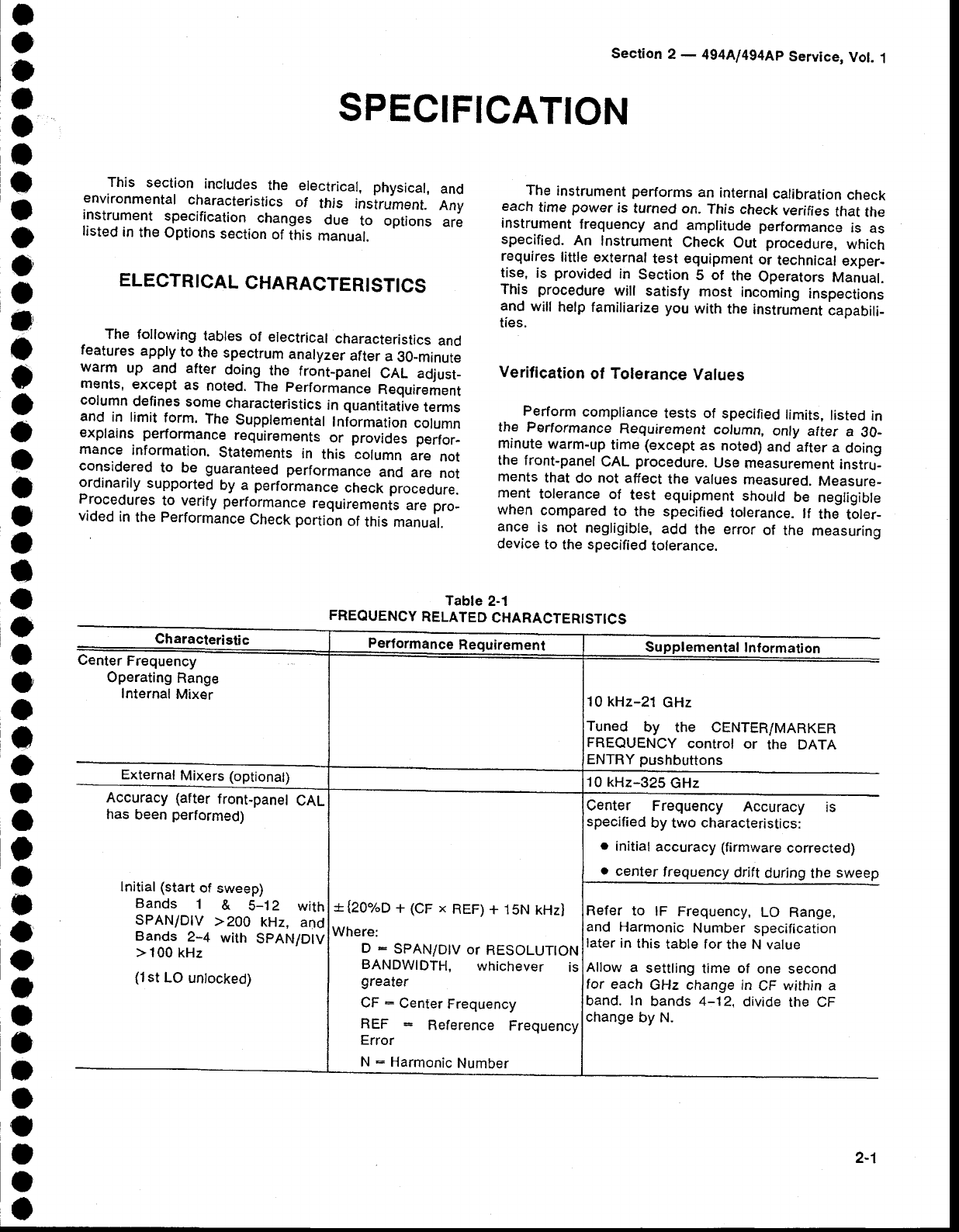
Table
2-1
FREOUENCY
RELATED
CHARACTERISTICS
The
instrument
performs
an
internal
calibration
check
each
tirne
power
is
turned
on.
This
check
verifies
that
the
instrument
frequency
and
amplitude performance
is
as
specified.
An
Instrument
Check
Out
procedure,
which
requires
little
external
test equipment
or
technical
exper-
tise,
is
provided
in
Section
5 of
the
Operators
Manual.
This
procedure
will
satisfy
most incoming
inspections
and
will
help familiarize
you
with
the
instrurnent
capabili-
ties.
Verification
of
Tolerance
Values
Perform
compliance
tests of
specified
limits,
listed
in
the
Performance
Requirernent
colurnn,
only
after
a
30_
minute
warm-up
time
(except
as
noted)
and
atter
a
doing
the front-panel
CAL
procedure.
Use
measurement
instru-
ments
that
do
not
affect
the values
measured.
Measure_
ment
tolerance
of
test
equipment
should
be
negligible
when
compared
to the specified
tolerance.
lf
the
toler_
ance
is not
negligible,
add
the
error
of
the
measuring
device
to
the
specified
tolerance.
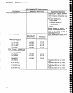
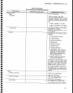
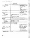
Characteristic
Performance
Requirement
Supplemental
Intormation
Center
Frequency
Operating
Range
Internal
Mixer
10 kHz-21
GHz
Tuned
by
the CENTER/MARKER
FREQUENCY
control
or
the DATA
ENTRY
pushbuttons
External
Mixers
(optional)
10 kHz-325
GHz
Accuracy (after
front-panel
CAL
has
been
performed)
lnitial (start
of
sweep)
Bands
1
&
5-12
with
SPANiDIV
>200
kHz,
and
Bands
2-4
with
SPAN/D|V
>100
kHz
(1st
LO
unlocked)
*{2Oo/oD
+
(CF x
REF)
+ 15N
kHz)
Where:
D
:
SPAN/D|V
or
RESOLUTTON
BANDWIDTH,
whichever
is
greater
CF
-
Center
Frequency
REF
Reference
Frequency
Error
N
:
Harmonic
Number
Center Frequency
Accuracy
is
specified
by two
characteristics:
.
initial
accuracy (firmware
corrected)
o
center
frequency
drift
during
the
sweep
Refer to
lF
Frequency,
LO Range,
and
Harmonic
Number
specification
later in
this
table for
the N value
Allow a
settling
time of
one second
for
each
GHz change in
CF
within a
band.
In
bands
4-'12,
divide
the CF
change
by N.
2-1