


Adjustment
Procedure
-
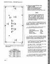
494[l4g4Ap
Service Vot.
1
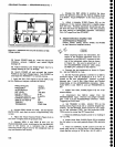
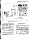
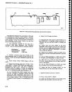
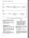
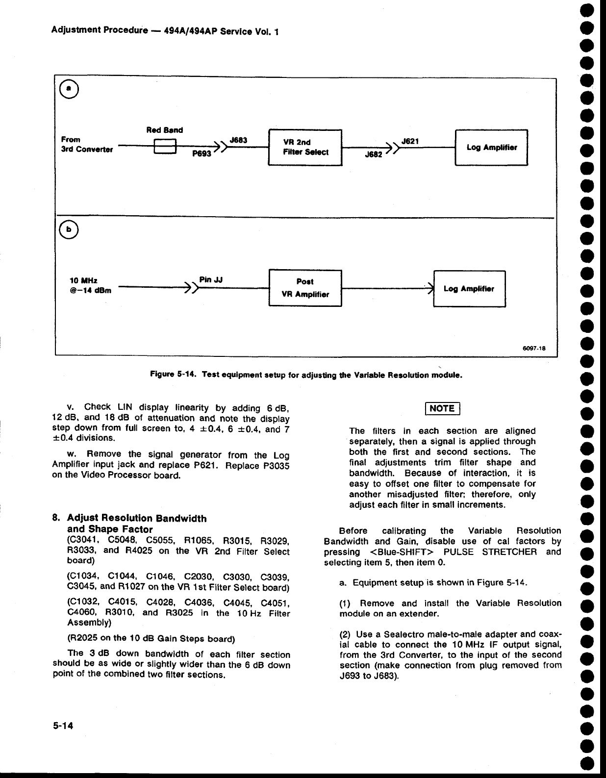
Figurc
5-14.
Test
equipment
3etup
tor
adiusting tlre
Varlable Re3olution
rnoOut".
5[ton'"*'
ffi
I
Filrc.
sotocr
I
6097-18
,
o
o
a
o
o
o
a
o
o
a
o
o
o
o
o
o
o
o
o
o
o
o
o
o
o
o
o
I
O
o
o
o
o
O
o
a
o
O
o
o
o
o
a
v.
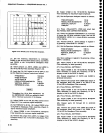
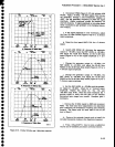
Check LIN
disptay linearity
by adding
6 dB,
12
dB. and 18
dB of
attenuation
and
note
the display
step
down
from
full
screen
to, 4
+0.4,
6
*0.4,
and
7
*0.4
divisions.
w.
Remove
the signal
generator
from
the Log
Amplifier input
jack
and
reptace
p621.
Reptace
p3035
on
the
Video
Processor
board.
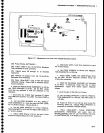
8. Adjust Resolution
Bandwidth
and
Shape
Factor
(c304r,
c5048,
C505s, R106s,
R3015,
R3029,
R3033, and
R4025
on
the VR
2nd
Filter
Setect
board)
(c1034,
C1044,
C1046,
C2030,
C3O3O,
C3039,
C3045,
and
R1027
on
the
VR
1st Fitter
Setect board)
(c1032,
C4015,
G4028,
C4036,
C4045,
C4051,
C4060,
R3010,
and
R3025
in
the 10
Hz Fitter
Assembly)
(R2025
on
the 10
dB
Gain Steps
board)
The
3
dB
down
bandwidth
of
each
filter section
should
be
as
wide
or
slighfly
wider
than
the 6
dB
down
point
of
the
combined
two
filter sections.
The
filters in each
section are
aligned
separately,
then
a
signal is applied
through
both
the first and
second sections.
The
final adjustments trim filter shape
and
bandwidth. Because
of
interaction,
it is
easy
to
offset
one
filter
to
compensate for
another
misadjusted
filter;
therefore,
only
adjust each
filter
in small increments.
Before calibrating
the
Variable Resolution
Bandwidth
and
Gain, disable use
of cal
factors
by
pressing
<Blue-SHIFT> PULSE STRETCHER
and
selecting
item
5, then
item 0.
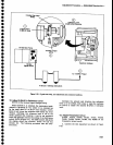
a.
Equipment setup is
shown
in Figure
5-14.
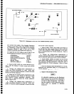
(1)
Remove and install the
Variable Resolution
module
on an extender.
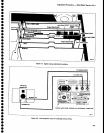
(2)
Use a
Sealectro male-to-male
adapter
ancl
coax-
ial
cable
to
connect the 10 MHz lF
output
signal,
from the 3rd Converter, to the
input of the
second
s€ction
(make
connection
from
plug
removed
from
J693
to
J683).
5-14