


o
o
o
O
a
o
o
o
o
o
o
o
o
o
o
o
o
o
o
o
o
o
o
o
o
o
o
o
o
o
o
o
o
o
o
o
o
o
o
o
o
o
o
o
7.
Reinstall
p361.
mounting
bracket
then
ptug
pg045
onto
th€
power
supply
board
anO
repacJ
the
cover.
8.
Set
the instrument
with
the
RF
deck
on
the
near
side.
then
hold
the
power
supply
module
at
the
rear
of
the
instrument
so
the right
side
is
touctring
the
side_rait
and
the
teft
side
is aboui
1.5
inch
above
iti
side-rait.
9.
Align
connectors
p5041
and
p1034
with
their
respective
Mother
board
and
Interface
board
connec-
tors'
then
press
the
modure
into
prace
beh^/een
the
side
rails.
10.
Replace
the
four
module
holding
screws
and
the
thre€
flange
screws.
11.
Reconnect
the.coaxial
cables
and
GplB
cable,
if
appropriate,
then
installthe
cable
clamp.
12.
Replace
the
instrument
cover.
High
Vottage
power
Suppty
A screw
must
be
removed
before
the
High
Voltage
Power
luqpty
circuit
board
can
Oe
unplugged
and
removed.
The
screw
goes
througt
tt"
iib"-rail
into
a
nylon
standoff
bushing
at
the
bottom
corner
of
the
board.
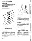
Removing
and
Replacing
the
lst
LO
.
1.
Unplug
and
remove
the
multipin
connectors
to
the assembty.
Cut
the
tie_down
thai
hoids
the
black
encased
RF
coil
to
the
semi-rigid
cable.
..
2.
Using
a
S/1
6
inch
open-end
wrench,
toosen
and
disconnect
the
semi-rigid
coaxial
cable.
3.
Loosen
and remove
the
four
mounting
screws
that
hole
the assembly
to
the
RF
deck.
Remove
the
1st
LO
assembly.
4.
To
replace
the
assembly,
reverse
the
removal
procedure.
Use
a
tie_down
to ri-tie
the
RF
coil
to
the
semi-rigid
cable
to
prevent
vibration
from
breaking
the
coif
leads.
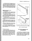
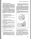
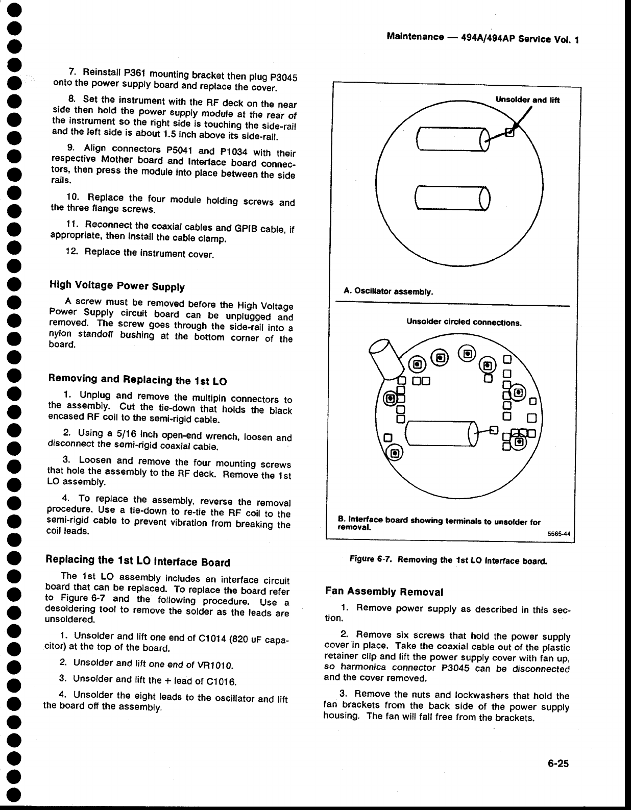
Replacing
the 1st
LO
Interface
Board
The
1st
LO
assembly
includes
an
interface
circuit
board
that
^c1n
be
reptaced.
To
replace
the
board
refer
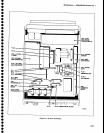
to Figure
6-7 and
the
following
procedure.
Use a
desoldering
tool
to
remove
tne
sotOlr
as
the
teads
are
unsoldered.
1.
Unsolder
and
tift
one_end
of
C1014
(g20
uF
capa_
citor)
at
the
top of
the
board
2.
Unsolder
and
tift
one
end
of
VRl010.
3.
Unsolder
and
lift
the
+
lead
of
C1016.
4.
Unsolder
the
eight
leads
to
the oscillator
and
lift
the
board
off
the
assembly.
Malnfenance
-
4g4Ll4g4Ap
Service
Vot.
1
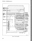
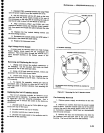
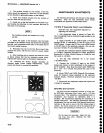
Figure
6-7.
Removing
the
lst
LO
Intertace
board.
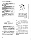
Fan
Assembly
Removal
1. Remove
power
supply
as
described
in
this sec_
tion.
2.
Remove
six screws
that hold
the
power
supply
cover
in
place.
Take
the coaxial
cable
out
of
the
plastic
retainer
clip
and
lift
the
power
supply
cover
with
fan
up,
so
harmonica
connector
pgO4S
can
be
disconnected
and
the cover
removed.
3.
Remove
the nuts
and
lockwashers
that hold
the
fan
brackets
from
the
back side
of
the
power
supply
housing.
The
fan
will
fall
free from
the
brackets.
A.
Oscillator
assembly.
Unsolder
circled
connections.
B.
Interface
board
showing
terminals
to unsolder
for
removal.
tr\
o\
pJ
trD
ff
@o
@@
DOU
6-25