


o
o
o
o
o
I
o
a
O
I
a
a
o
t
o
I
I
I
I
o
a
t
a
O
t
o
o
o
t
a
o
a
I
a
o
a
I
a
o
o
o
o
o
I
07)
Move
p2035
back
to
pins
1
and
2,
reptace
P3057,
and
disconnect
the
iest
oscilloscope
from
the
Error
Amplifier
board.
(18)
Reduce
SPAN/D|V
to 200
kHz
and
ensure
that
phase
lock
occurs,
by
the
absence
of error
rnessage
and
a sweep.
Replace
the
covers
on
the assemdly
and
reinstall
the
module
in
the
lnstrument.
perform
the
phase
lock
noise
check
as
described
in
the
per-
formance
Gheck
section.
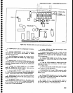
h.
Check
Strobe
Drlver
-
Excessive
noise
on
the
display
and
intermittent
lock
are
indications
that
the
strobe
pulse
from
the
Strobe
Driver
is
noisy
or
tow
in
amplitude.
This
can
be caused
by a
mismaich
in
input
g
o$qut
impedance
to
th€
band-pass
fitter
FL20Li4.
The
folfowing
procedur€
is
required
if
the filter
or
any
component
that affects
the
input
or
output
impedanc6
match
is
replaced.
(1)
With
the
instrument
in
phase
lock
rnode
(SPAN/D|V
200
kHz
or tess),
monitor
Tp1Og2
with
a
test,oscilloscope.
Note
the amplitude
of
the
5 MHz
strobe
signal.
Amplitude
of
the sinusodial
strobe
signal
is normaily
5 V
to
6 V
peak-to_peak.
(2)
lf
the strobe
signal
amplitude
is
low
and
noisy,
change
the value
of
select
capacitors
C1016,
C.t 016;
C1032
and
C1034
to
obtain
the
maximum
strobe
pulse
amplitude
at
Tpl0g2.
These
capacitors
range
from
3.3
pF
to 27
pF.
(3)
lf
the signat
amplitude
is
still
tow,
check
the fre_
quency
at
TP1012
with
a
frequency
counter.
Fre-
quency
must
fie
between
5.0067
MHz
and
5.0188
MHz.
The
frequency
is a
function
of
the
Controlled
Oscillator
assembiy
and
counter
U1OZ2.
Adjustment
Procedure
-
4g4[l4g4fup
Servlce
Vol.
1
c.
lt
may
be necessary
to set
th€
FREQUENCy
con-
trol
to
ke€p
the 100
MHz
signal
at center
screen.
d.
RESET
thE
RESOLUTION
BANDWIDTH
tO
300
kHz,
and
the
VERTTCAL
DtSpLAy
to 2
dB/DtV.
e.
Set
the
front-panel
AMPL
CAL
for
a
7-division
excursion
of
the 100 MHz
signat.
f.
Flemove
the
50O cable
from
the instrument
and
reconnect
the
cAL
ouT
signal
to
the 75o
RF
INpUT
via
a
75O
cabl€.
Push
the 75O
RF tNpUT
button.
g.
Reset
the
REFERENCE
LEVEL
to +20
dBmV
h.
Adjust
R3024 on
the
VR
Mother
board
#Z
tor a
7-division
excursion
of
the
100
MHz signal.
i.
Disconnect
the 75O
cable,
disable
the 7SO
input,
and
re-fnstall
the VR
module
in the spectrum
analyzer.
18.
Adjust
Option
42
Modute
(Cl016,
Cl020
and
Cl024
in
the
Option 42
Moctute)
This
adjustment
n€ed
only
be
done after
the
circuit
board
in
the module
has
been
replaced.
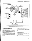
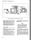
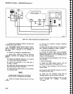
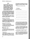
a.
Connect
the
test equipment
as
shown
in
Figure
5-27.
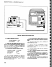
b.
Set the front-panel
controls of
the
test
instrument
as
follows:
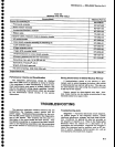
OPTION
INSTRUMENTS
ONLY
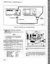
17.
Adjust
Option
0Z VR
Band
Levetino
(R3024
on
the VR
Mother
board
#2)
a.
Set
the front-panel
controls
as
follows:
FREQUENCY
.t00
MHz
FREQ
SPAN/D|V
200
kHz
REF
LEVEL
_20
dBm
MIN
RF
ATTEN
O
dB
AUTO
RESOLN
on
TIME/DIV
AUTO
VERT|CAL
DISPLAY
10
dB/Dtv
vtEW
A/V|EW
B
On
b. Place
the VR
module
on
an
extender,
and
con_
nect
the
cAL
ouT signat
to
the
50o
RF
tNpUT
via a
50O cable.
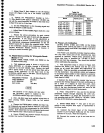
TR5O2
Output
Level
-dBm
25
Var
dB
0
7L14
CenterFrequency
0110
Freq
Span/Oiv
2
MHz
Resolution
3
MHz
Vertical
Display
2 dB
Reference
Level
DisplayAandB
Off
DC503A
chA
Term
50O
Slope +
Atten
Coupl
dc
Freguency
A
Autotrig
5-29