


o
o
o
o
o
o
t
t
o
I
o
O
o
O
o
o
o
a
o
o
o
o
o
a
a
o
O
o
o
a
o
O
o
O
o
o
O
o
a
o
o
o
o
o
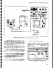
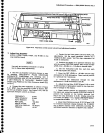
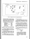
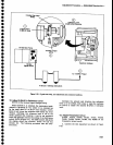
Flgure
5'15.
Adiu3tmonts
on
the
rear
of tre Variabre
Resorudon
modure.
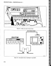
(3)
Connect
the
output
of
the
Variable
Resolution
module
to the
input.
of
lhe
Log
Amplifier
assembly
by connecting
a cable
from
J6g2
on
the Variable
Resolution
Module
to
J621
on
th€
Log
& Video
Amplifier
assembly
{see
Figures
S-10 and
-S-t+;.
(a)
Apply
the
CAL
OUT signat
to
th€ RF
tNpUT,
and
set
the
Spectrum
Analyzer
controls
as
follows:
FREQUENCY
100
MHz
FREO
SPAN/D|V
S0 kHz
RESOLUTTON
BANDWTDTH
10
kHz
REF LEVEL
-20dBm
MtN
RF
ATTEN
0 ctB
VERTICAL
DTSPLAY
2
dBl}tv
b.
Reset
the
REF
LEVEL
for
a
seven
division
excur_
sion
Tune
the
display
to
center
screen
and
activate
SAVE
A.
-
c.
Change
the
RESOLUTTON
BANDWIDTH
to
3
MHz
and
FREQ
SPAN/D|V
to 1
MHz.
Reset
REF
LEVEL
to
bring
the signal
amplitude
to about
the
same
level
as
th€ 10 kHz
response.
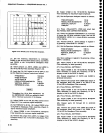
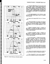
-d.
Adjust
the four
tuning
screws
(capacitors)
on
the
110
MHz
Bandpass
Fitter (FL361
foi
tire
best
3
MHz
fi-lter
.
response
(3
MHz
bandwidth
*600
kHz,
6 dB
down)
that
is
centered
about
the
10
kHz
reference.
Refer
to
Figure
5-1
6.
e.
Change
the
RESOLUTTON
BANDWIDTH
ro
1 MHz
and
FREQ
SPAN/D|V
to 500
kHz.
Reset
REF
LEVEL
to
bring
the signal
amplitude
to about
the
same
level
as
th€
10 kHz response.
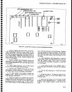
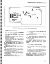
f.
Adjust
C1034,
C1044,
and
C1046,
and
R1027
on
the VR
2nd Filter
Select
board (Figure
5,15) for
the
best
1
MHz
filter
response
(1
MHz
bandwidth,
3
dB
down.
that
is centered
about
the 10
kHz
reference).
Refer
to
Figure
5-16.
g.
Change
the
RESOLUTTON
BANDWTDTH
ro
100
kHz
and
reset
REF LEVEL
to bring
the
signat
ampti-
tude
to about
the same
level
as
the
l0 kHz
response.
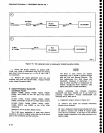
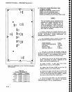
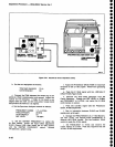
h.
Adjust
C5055,
C5048, and
C3041
on
the VR
2nd
Filter
Select
board
(Figure
5-17)
for
the best
.lOO
kHz
filter
response
(100
kHz
bandwidth,
3 dB
down,
that
is
centered
about
the 10 kHz
reference).
Refer
to Figure
5-1
6.
i.
RESET
th€ RESOLUTION
BANDWIDTH
tO 1O KHZ,
deactivate
and
reactivate
SAVE A
to
re-establish
the
10
kHz
reference.
n
r(
',
-'
-5
-
J.
Adlust
10 Hz
All
adjustable
capacitors
on
the Bandpass
Fifter
board
in
the
10
Hzfi00
Hz Bandpass
Filter
assembly
should
be
set
to midrange
if
the
filter is
badly misadjusted.
This minim-
izes
the number of
times
interacting
adjust-
rnents
must
be repeated
to
eliminate
interaction.
Bandpass
Fllter
lNorE-l
AdJustment
Procedure
-
4g4[l4g4Ap
Service
Vot.
1
5-15