


o
a
o
o
t
o
t
o
o
I
o
a
o
t
a
O
a
o
o
o
a
a
o
o
o
o
O
o
o
o
o
o
o
o
o
o
o
o
o
o
o
a
o
o
829
MHz
Converler
Maintenance
Some
circuit
boards
in
this
assembly
contain
critical-length
printed
elements.
When
damaged,
these
elements
are
usually
not
repairable;
therefore,
the
cir_
cuit
board
must
be replaced.
even
itroujfr
repfacement
bgards
.are
precalibrated
and
,"p"i,
"-"n
be
accom_
plish.ed.by
replacing
the
board,
we
recommend
sending
the
instrument
or
assembly
to
your
Tekironix
Service
Center
for
repair
and
calibrition.
-
The
829
MHz
band-pass
filter
in
the
lF
section,
and
the 7'l9
MHz
LO
in
the
-Lo
section,
require
adjustment
only
if
the
board
has
been
damaged'J,
""tiu"
"o*-
ponents
(transistor
or
varactor)
hive
been
reptaced.
The following
describes
prepaiation
foi
service
and
replacement
procedures.
The
first
two steps
describe
how
to
gain
access
to either
the
LO
or
the
lF
section;
the.remaining
st€ps
describe
adjustment
procedure
for
each
section.
1.
To
gain
access
to the
LO
section:
a.
Switch
POWER
ofi;
use
a
5/64
Ailen
wrench
to
loosen
and
remove
the
cover
screws.
b.
Remove
the cover.
c.
Refer
to
step
3
(within
this
procedure)
for
adjust-
ment
procedure.
2.
To
gain
access
to
the
lF
section
a.
Switch
POWER
off;
use
a
5/16
inch
wrench
to
disconnect
and
remove
all
coaxial
connectors
to
the
829 MHz
converter.
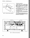
b. Remove
the
six
mounting
screws,
unplug
the
input
power
connector
P4OSO,
ihen
remove
the
g2g
MHz
converter
assembly.
c.
Turn
the
assembly
over
and
remove
the
cover
for
the lF
section.
d. To
troubteshoot
or
calibrate
the
circuits,
set
the
assembly
at
a
location
so
the input power
plug
p4050
can
be reconnected
to
the
Mother
boarO.
Be
sure
to
observe plug
orientation
(pin
1
to
pin
1).
e.
Refer
to step
4
(within
this
procedure)
for adjust-
ment
procedure.
3.
719
MHz
Osciilator
Range
Adjustment
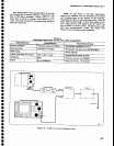
a.
Adjustment
requires
the
foilowing
test equip-
ment:
| ^frequency
counter
with
a
frequency
range
to
1
GHz
(nine
digit
readout),
sensitivity
of
20
mV
rms
for
prescaled
input
or
15
mVrms
tor
a
direct
input
(such
as
TEKTRONIX
Dc
510 counter
with
a Dp
501
pres.calee;
a
digital
voltmeter
with
a
g.5
digit
readout (such
as
TEKTRONIX
DM
502A);
test teads
Maintenance
-
4g4N494Ap
Servtce
Vol.
1
for
th€ DVM,
a
50O coaxial
cabte
with
bnc
connec_
tors
ffektronix
part
number
012-04g2_00)
and
a
sma
male-to-bnc
f_emale
adapter
Cfektronix
part
number
015-1018-O0).
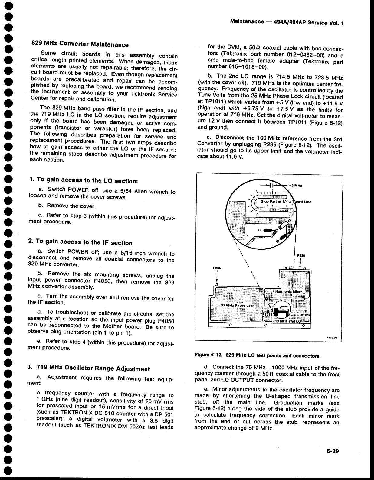
b. The
2nd
LO
range
is 714.5
MHz
to
223.5
MHz
(with
the cover
off).
71g
MHz
is
the optimum
center
fre_
guen!{.
.
Frequency
of
the osciltator
is
controlled
by
the
Tune
Volts
from
the 25
MHz
phase
Lock
circuit
ltoiateO
at
TPl011)
which
varies
from
+5
V
(low
end)
to
+11.g
V
(high
end)
with
+6.75
V
to
+2.5
V
as
the
timits
for
op€ration
at
719
MHz.
set
the
digital
voltmeter
to meas_
ure 12
V
then
connect
at
between
Tplolt
(Figure
6-12)
and
ground.
c.
Disconnect
the 100
MHz
reference
from
the
grd
Converter
by
unplugging
p235
(Figure
6-12).
The
oscit_
lator
should
go
to
its
upper
limit and
the
voltmeter
indi-
cate
about
1
1.9
V.
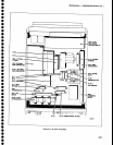
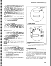
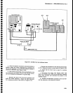
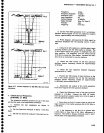
Figure
6-12.
829
MHz
LO
test
points
and connectors.
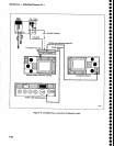
d.
Connect
the 75
MHz-1
000 MHz input
of
the fre-
quency
counter
through
a
50O
coaxial cable
to the front
panel
2nd
LO
OUTPUT
connector.
e.
Minor
adjustments
to the
oscillator frequency
are
made
by
shortening
the
U-shaped
transmission
line
stub,
off
the
main line.
Graduation
marks
(see
Figure
6-12)
along
the side
of
the stub
provide
a
guide
to calculate
frequency
correction.
Each
minor
mark
from
the end
or
cut
across
the stub,
represents
an
approximate
change
ot 2
MHz.
6-29