


Theory
of
Opera$on
-
4944/4g4Ap
Servtce,
Vol.
I
off.
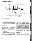
Negative current.
supplied
through
Rl014,
€nsures
that Q1011 is
turned off.
Diode
CRt011
protects
the
base of 0101 1 from
excessive
reverse
bias. Voltage
across
R1017 is
approximately
9.4 V
when
e1011 ls
turned
on and approximately
4.4V
when
it
is off.
Overall
gain
is
approximately
12.9
dB
when
the
amplilier
is
turned
on.
The
110 MHz lF
signal
is
transmitted
via
p2g2
to the
110
MHz lF Amplifier
shown
on
diagram
17.
LO
Section
(Diagram'15)
The
829 MHz 2nd
Converter
LO
generates
the
719
MHz frequency
that is
mixed
with
the
929 MHz
tF
to
produce
th€ 110MHz
lF signat.
ln
the
following
description,
the
circuits
are referred
to
as
the
71
g
MHz
LO. The 719MHz
LO consists
of
a
phase
lock
loop,
a
719 MHz output
circuit,
and
a 2nd
LO front paneloutput
circuit.
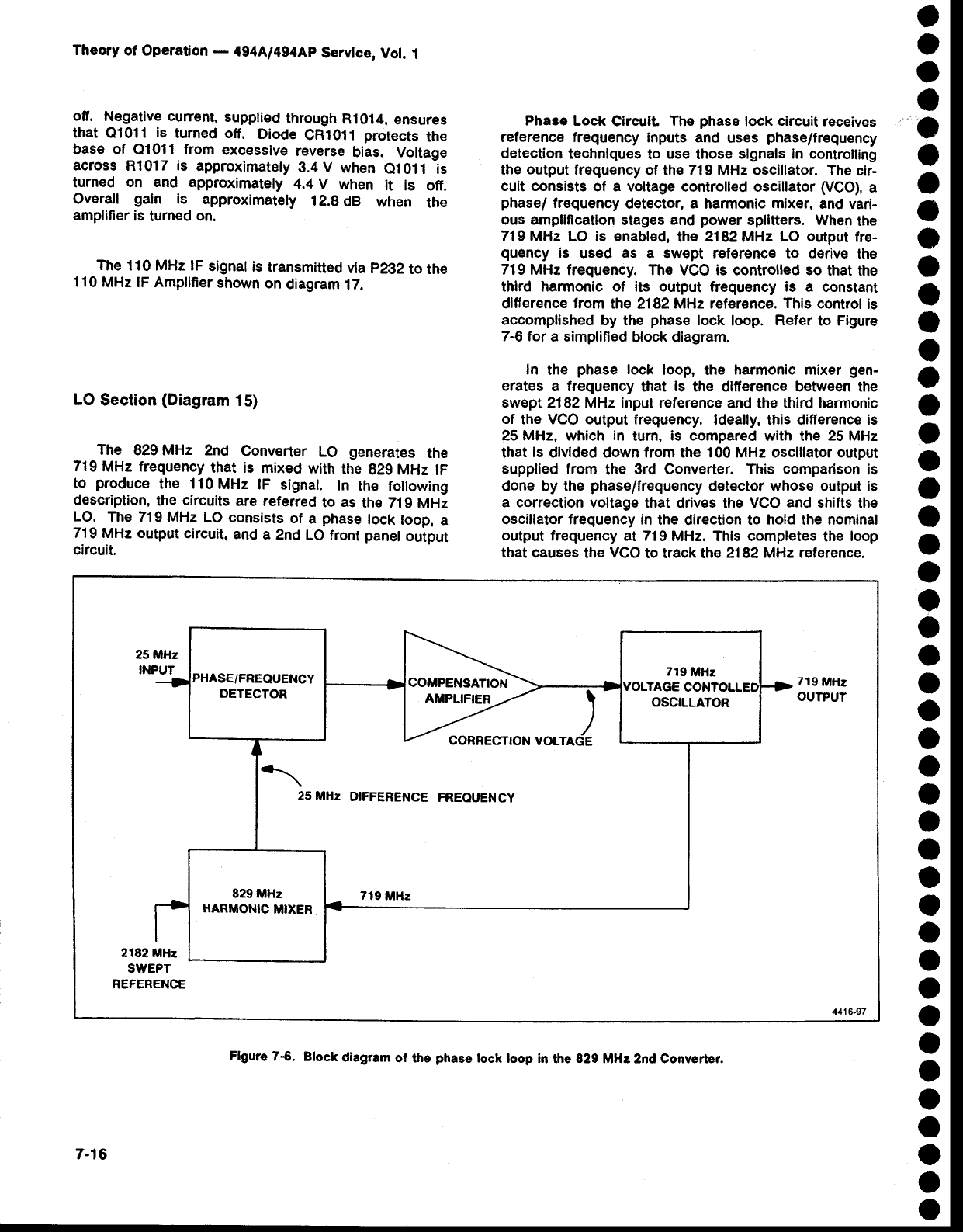
Phase
Lock
Circult
The
phase
lock
circuit
receives
reference frequency
inputs
and uses
phase/frequency
detection
techniques
to
use
those
signals in controlling
the
output
frequency of
the
719 MHz oscillator. The
cir-
cuit consists
of a voltage
controlled oscillator
(VCO),
a
phase/
frequency
detector,
a
harmonic
mixer,
and vari-
ous amplification
stag€s
and
power
splitters.
When
the
719
MHz LO is enabled,
the 2182MHz
LO output
fr€-
quency
is
used
as
a swept r€f€rence to
d€rive
the
719
MHz
frequency. The VCO is controlled so
that
the
third harmonic of its output
frequency is a constant
difference
from
the
2182MHz
reference. This control
is
accomplished
by the
phase
lock
loop.
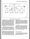
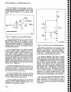
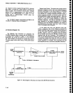
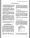
Refer
to Figure
7-6 for
a simplified
block diagram.
In
the
phase
lock
loop,
the
harmonic
mixer
gen-
erates
a frequency
that
is
the difierence between
the
swept 2182
MHz
input reference and
the
third
harmonic
of
the
VGO
output frequency.
ldeally,
this
difference is
25 MH4 which
in
tum.
is compared
with the
25
MHz
that
is
divided down from the 100 MHz oscillator output
supplied
from
the
3rd Converter. This
comparison
is
done by the
phase/frequency
det€ctor
whose output is
a correction
voltage
that drives the
VCO
and
shifts
the
oscillator frequency in
the
direction
to hold the nominal
output
frequency at 719
MHz. This completes
the
loop
that
causes the vco
to track the
2182 MHz reference.
t
t
o
a
o
o
a
I
o
o
o
o
o
o
O
O
o
o
o
O
o
o
o
o
o
o
o
o
a
a
a
o
o
o
I
o
o
o
o
o
a
O
a
o
PHASE/FREOUENCY
DETECTOR
COMPENSATION
AMPLIFIER
OSCILLATOR
25
MHz
DIFFERENCE
FREOUENCY
829 MHz
HARMONIC
MIXER
7-16
Figure
7$.
Block
diagram
of the
phase
tock
loop
in the
829
MHe 2nd Converter.