


Malntenance
-
4tt0[l4g4Ap
Servlce
Vol.
I
Because
the frequency
control
loop
may
be
unlocked
when
using
the
internal
reference
freguency
in
a
ucold'
instrument.
no
error
messag€
is
displayed
for
the internal
refer-
ence
unlocked
condition.
How€ver,
l_U
(lnternat-Untock)
is
disptayed
at
the
REFER-
ENCE
OSCTLLATOR positaon
for
the
normal
instrument
rEadout.
The
proc€dure
that
deats with
FREQUENCY
REFERENCE
UNLOCKED
message
shoutd
be foilowed
if
l-U
appears
after
the
instrument
is
warm.
The
following
troubleshooting
procedures
are
keyed
to the
brief
error messages.
Some
problems
may
pro-
duce more
than one
error
message
in
which
caje'the
spectrurn
analyzer
will
<lisplay only
th€
predominant
error.
A listing
of all
error
m€ssages
will
be
displayed
if
you
press
<Blue-SHIFT>
MAX
HOLD.
Combinations
of error
m€ssages
may
help
determine
and
expedite
the
proc€ss
of
finding
the
problem.
. .
Some of
the
procedures
use
firmware
diagnostics
aid
routines
which can
only
be
accessed
by
pressing
>Blue-SHIFT>
PULSE
STRETCHER
anO-
ietecting
menu
item
#3
(DIAGNOST|C
A|DS).
Combination
of Error
Messages
The
following
is
a list
of
error
m€ssage
combina-
tions
and
suggestions
as
to their cause.
lf
the
problem
is
not resolved
with
the
following
suggestions.
or
if the
combination
of
effor
messages
displayed
is
not
covered,
proceed
to
the listing
of
each
error
message
and
how
to troubleshoot
the
problem.
POWER
SUPPLY
OUT
OF REGULATION
(in
comblnatlon
wlth any
otfrer
meseage/s)
A
missing
or
inaccurate
supply
voltage
is
probably
causing
the other errors.
proceed
to
the
POWER
SUp-
PLY
OUT
OF REGULATTON procedure.
TUNING
FAILURE
-
lST
LO
and
TUNING
FAILURE
-
2ND
LO
The
CF
Control
board
is
probably
the
cause,
partic-
ularly if signals
do
not
tune or
do not
tune
smoothly.
The
problem
is
probably
the voltage
reterence
or in
the
digital control
section.
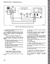
Procedure
Format
The
format
for
thes€
procedures
is
such
that the
problem
is
diagnosed
in
a
dEscending
order.
The aim,
to
isolate
a
problem
down
to one
part
of
the
system,
usuaily an
assembly
(such
as
a module
or
boardl
or a
functional
section
of
the assembly.
After
the
pr6btem
6-5
1.
has
been isolated
to the
assembly
or circuit
level,
refer
to
the diagrams
and circuit
descr{ption,
as
suggested
under
General Troubleshooting
Technigues,
for
further
isolation.
The
procedures
are structured
as follows:
Error
Message
Troubleshooting
Procedure
Steps
at
the same
level
are
either
sequential
or
alternative steps,
based
on
measurement or
observa-
tion.
Proceed
to
the lower-level steps
only
if
the
condi-
tions
of
the
higher-level
steps are
met. lf
the
conditions
are not
met,
proceed
to
the
next
step at
the
same
level.
An "(E)'
at
the
end
of
a step,
signifies
this
is as
far as
this
procedur€
can
tak€
you
to locate
the
problem.
Several of
the troubleshooting
procedures
require
that frequencies
be
counted and compared
to
either
an
expected
value, or
the
number counted
by
the spectrum
analyzer's internal
counter.
The frequencies
can
differ
by up to
[(1x10⁷)
+
(counter
accuracy).
These
procedures,
unless
specifted,
assume
the
fre-
quency
range
is either
0
-
1.8
GHz or 1.7
-
5.5 GHz.
Some
failures,
in
the
frequency
control
system,
may
appear only
at sp€cific oscillator
frequencies. lf this
occurs,
in a higher
frequency range, the fundamental
frequency
of
the
appropriate oscillator should
be deter-
mined
so
it can
be
set
to
the same
frequency
in
the
lower
bands. This can
be done by:
a.
b.
(1)
(2)
2.