


o
a
a
o
o
o
o
o
o
o
o
a
o
o
o
t
O
I
o
o
e
a
o
o
o
c
o
o
I
o
o
a
o
o
a
o
a
o
o
O
o
O
o
o
lf
you
desire
to remove
the component
l€ads,
use
a
J.5 Y
ol
tess
pencil
type
iron.
Straigtrten-the
teads
on
me
oacK
side
of
the board;
then
when
the
sotder
melts,
gently
puil
the
sotdered
tead
through
the
hote.
A
desoldering
tool
should
be
used
to
-remove
the
old
solder.
Use
a
desoldering
toot
that
has
a
low
build-up
of
static
charge,
such
as
SiMerstat
Soldapullt
desolder-
ing
tool,
when
unsoldering
integrated
circuiis
or
transis_
tors.
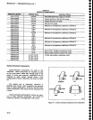
Replacing
the
Square
pin
tor
the
Multi-pin
Connsctors
It
is
important
not
to
damage
or
disturb
the
ferrule
when
removing
the
old
stub
of
a
broken
pin.
Tne
ter_
rule
is
pressed
into
the circuit
board
and
provides
a
base
for
soldering
the
pin
connector.
lf
the
broken
stub
is
long
enough,
grasp
it
with
a
pair
of
needle
nose
pliers,
appty
treatl
wiih
a small
sold-
ering
iron,
to
the
pin
base
of
ine
ferrute
and
pull
the old
pin.
out.
(Ihe
pin
is
pressed
into
th€
terruie
so
a
firm
pull
is
r€quired
to
pult
it out.)
lf
the
broken
stub.is-too
short
to
grasp
with
pliers,
use
a small
dowel
(0.029
inch
in
diameter;
clamped
in
a
vise
to.push
the
pin
out
of
the
ferrule
after
the solder
has
melted.
The
old
ferrule
can
be
cleaned
by
reheating
socket
and
placing
a
sharp
object
such
as
a
toothpicklr
small
dowel lnto
the
hote.
A
O.Ogl
inch
driil
mounted
in
a
pin
vise
may
also
be
used
to
ream
the
solder
out ol
the
old
ferrule.
-
Ur."
a
pair
of
diagonal
cutters
to remove
the ferrule
from
the new
pin;
then
insert
the
pin
into
the otd
ferrule
and
solder
the
pin
to both
sides
oi
the
ferrute.
.
lf
it-is,-necessary.to
bend
the
new
pin,
grasp
the
base
of
the
pin
with
needle_nose
pliirs
and
bend
against
the
pressure
of
ths
pliErs
to avoid
breaking
the
board
around
the
ferrule,
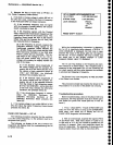
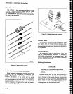
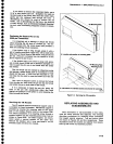
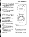
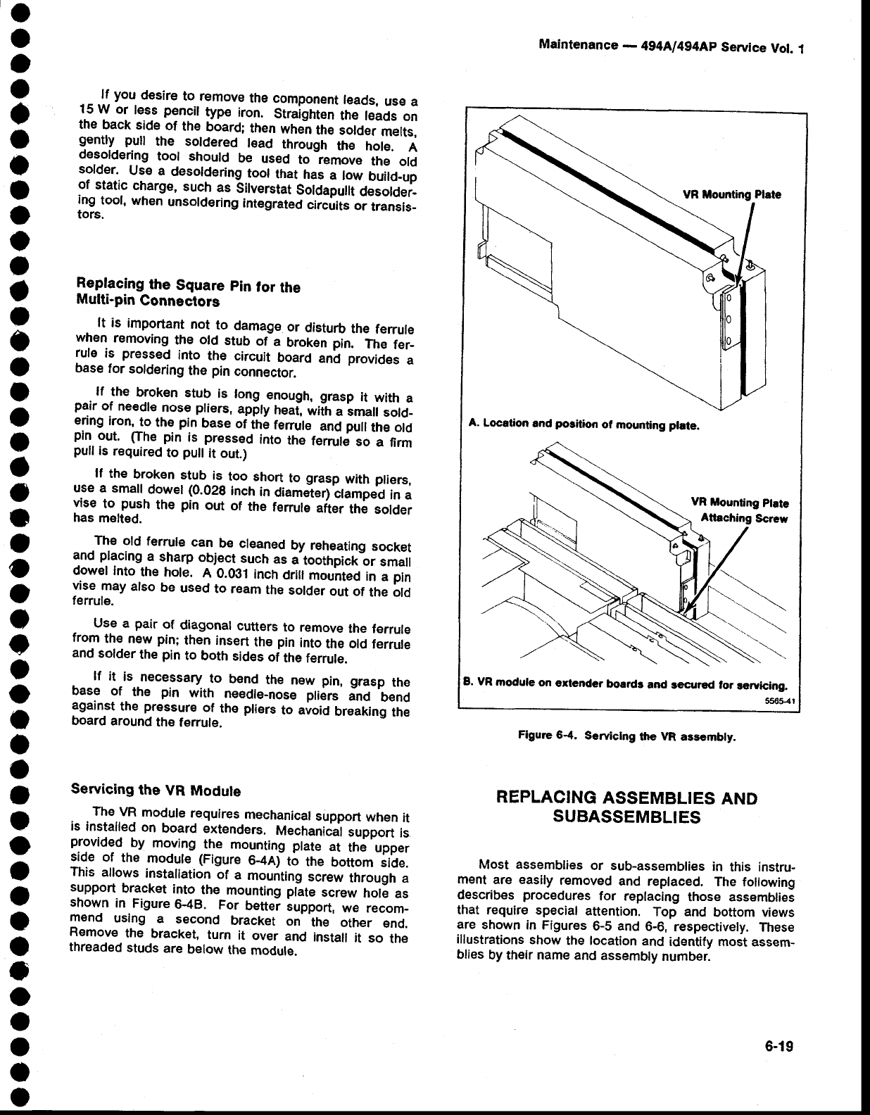
Servicing
the
VR
Module
The
VR
module
requires
mechanicat
support
when
it
is
installed
on
board
extenders.
Mechanical
support
is
provided
.
by
moving
the
mounting
plate
at
the
upper
:'.qe
of
the
modut€
(Figure
6_Anf
ti
the
bottom
sicte.
This
allows
installation
of
a
mounting
screw
through
a
support
bracket
into
the
mounting
plate
screw
hole
as
shown
in
Figure
6-48.
For
bettei
iupport,
we
recom-
mend
using
a
second
bracket
on
the
other
end.
Remove
the
bracket,
turn
it
over
and
install
it
so
the
threaded
studs
are
below
the
module.
Maintenance
-
494AJ494Ap
Service
Vot.
1
A.
Locetion
rnd
position
of
mounting plate.
VR
mounting
ptate
B, VR
module
on
€rtender
boards
and
secrred for
rervicing.
5565-41
Figure
6.4.
Serviclng
the VR
ass€mbly_
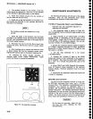
REPLACING
ASSEMBLIES
AND
SUBASSEMBLIES
Most assemblies
or sub-assemblies
in
this instru-
ment
are easily
removed
and
replaced.
The
following
describes
procedures
for
replacing
those assemblies
that require
special
attention.
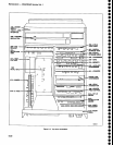
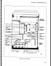
Top
and
bottom views
are
shown
in Figures
6-5 and
6-6,
respectively.
These
illustrations
show
the location
and
identify
most assem-
blies
by
their
name
and
assembly
number.
6-19