


o
a
a
o
o
I
o
o
o
a
o
)
t
o
t
o
I
a
t
a
o
e
a
a
t
o
t
o
o
o
t
o
o
o
I
o
I
o
o
o
o
o
I
o
Maintenance
-
494A1494Ap
Service
Vol.
1
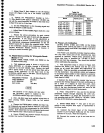
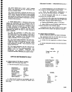
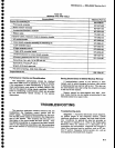
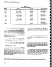
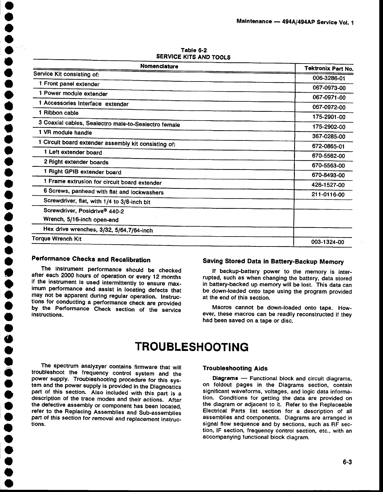
Table
6-2
SERVICE
KITS
AND
TOOLS
Nomenclature
Service
Kit consisting
of:
'l
Front
panel
extender
1 Power
module
extender
I Accessories
Interface
extender
1
Ribbon
cabte
3
Coaxial
cables,
Sealectro
male-to-S€atectro
temate
1 VR
module
handle
1
Circuit
board
extender
assembly
kit
consiiiing
of:
I
Left
€xtender
board
2
Right
exlender
boards
1
Right
GPIB
extender
board
1
Frame
eldrusion
for
circuit
board extender
6
Screws,
panhead
with
flat and
tockwasheii
screwdriver,
flat,
with
1/4
to
3lg-inch
bit
Screwdriver,
posidrive@
440-2
Wrench,
5/1
6-inch
open-end
Hex
drive wrenches,
glg2,
SI€/',ZlGzt-inch
Torque
Wrench
Kit
Tekfonix
Part
No.
006-3286-01
067-0973-00
067-0971-00
067-0972-00
175-2901-00
17$2902-00
367-028s,00
672-0865-01
670-5562-00
670-5s63-00
670-8493-00
426-1527-A0
21 1-01
16-00
003-1324-00
Saving
Stored
Data
in Battery-Backup
Memory
lf
backup-battery
power
to
the memory is
inter-
rupted,
such as
when
changing
the
battery, data
stored
in
battery-backed
up
memory
will
be
lost. This
data can
be
down-loaded onto
tape
using
the
program provided
at
the
end of
this section.
Macros cannot
be down-loaded onto
tape.
How-
ever,
these
macros
can
be
readily
reconstructed
if
they
had
been
saved
on
a
tape or
disc.
Performance
Checks
and
Recalibration
The
instrument performance
should
be checked
after
each
2000
hours
of operation
or
every
12
months
if
the
instrument
is
used
intermittently
to insure
max_
imum
performance
and
assist
in
lociting
defects
that
may
not
be apparent
during regular
operation.
Instruc_
tions for
conducting
a
performance
check
are
provided
by the
Performance
Check
section
of
the service
instructions.
Troubleshooting
Aids
Diagrams
-
Functional
block
and
circuit
diagrams.
on
foldout
pages
in
the
Diagrams
section,
eontain
significant
waveforms,
voltages,
and
togic
data informa-
tion.
Conditions
for
getting
the
data
are
provided
on
the
diagram
or
adjacent
to
it.
Refer
to the
Replaceable
Electrical
Parts
list section for
a
description of all
assemblies
and components.
Diagrams
are arranged
in
signal
flow sequence
and
by
sections,
such as
RF sec-
tion,
lF section, frequency
control
section, etc.,
with an
accompanying
functional
block diagram.
6-3
TROUBLESHOOTING
The
spectrum
analyzyer
contains
firmware
that
will
troubleshoot
the frequency
control
system
and
the
power
supply.
Troublsshooting
procedure
for
this
sys_
t€m
and
the
power
suppty
is
provided
ln
the Diagnostics
part
of
this section.
Also
included
with
this
part
is a
description
of
the
trace
modes
and
their actions.
After
th€
def€ctive
assembly
or component
has
be€n tocated,
refer
to
the Replacing
Assemblies
and
Sub_assemblies
pert
of
this section
tor
removal
and
repfacement
instruc_
tions.