


t
o
a
o
I
o
o
I
a
a
o
o
a
O
I
I
I
a
O
o
o
o
o
o
a
O
a
o
I
I
o
O
O
o
t
o
o
o
o
I
o
o
a
I
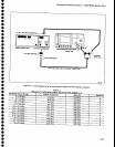
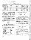
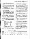
Cal Factor
Test
frequency
Mode
dBm
Range
Hotd
Out
.h.
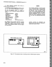
setthe
signat gen€rator
(Hp
g3508/s3595A)
con-
trols
as follows:
Performance
Check
procedure
-
4g4Al4g4Ap
Servlce
Vol.
1
Frequency
Mode
CW
Frequency
Test
Frequency
Output
Level --5
dBm
i.
Set
the
generator
controls
for
a
-15
dBm
power
meter
reading
(approximately
-5
dBm
generator
output
Ievel).
j.
Tune
the
CENTER
FREQUENCY
controt
to
brino
the signal
to
center
screen.
k.
The
Spectrum
Analyzer
should
be
displaying
a
signal
of
approximately
-35
dBm.
l.
Use
the
Spectrum
Analyze/s
AMPL
CAL
control
to
position
the signal
peak
at
a convenient graticule
line,
then activate
SAVE A.
m.
Establish
a reference
setting
for
the first
10
dB
incrernent
by
pressing
dB[Ref
on
the
power
meter.
n.
Reset
the MIN
RF
ATTEN
dB control
to 10
and
the REFERENCE
LEVEL
to
-20
dBm.
Reset
the
gen-
erator
output
level
for
a
power
meter
reading
of +1
0 dB
(1
0 dB
increase
in output
level).
c.
Disconnect
the
power
sensor
from
the
power
divider,
and
connect
it
to
th€
the
I
,WISO
MHz
refer-
ence
output
port
through
an
appropriate
adapter.
Be
sure
that
the
50 MHz
reference
is'tumed
off.
-
d.
On
the
power
meter,
press
Sensor
Zero
and
wait
for
the-zero
light
to
turn
off.
Repeat
until
a
zero
is
attained.
e.
.On
the
power
meter,
set
the
50 MHz
reference
on
and
set
the
Cal
Factor
switch
to
the
50 MHz
refer-
ence..
Set
the
power
meter
Cal
Adj
for
a
1.000
mW
reading.
f.
Turn
off
the
50
MHz
reference
on
the
power
meter,
and
reconnect
th€
power
sensor
to
th€
power
divider.
g.
Reset
the
power
meter
controls
as
follows:
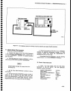
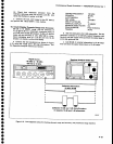
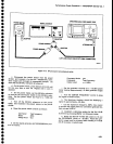
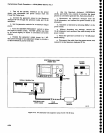
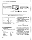
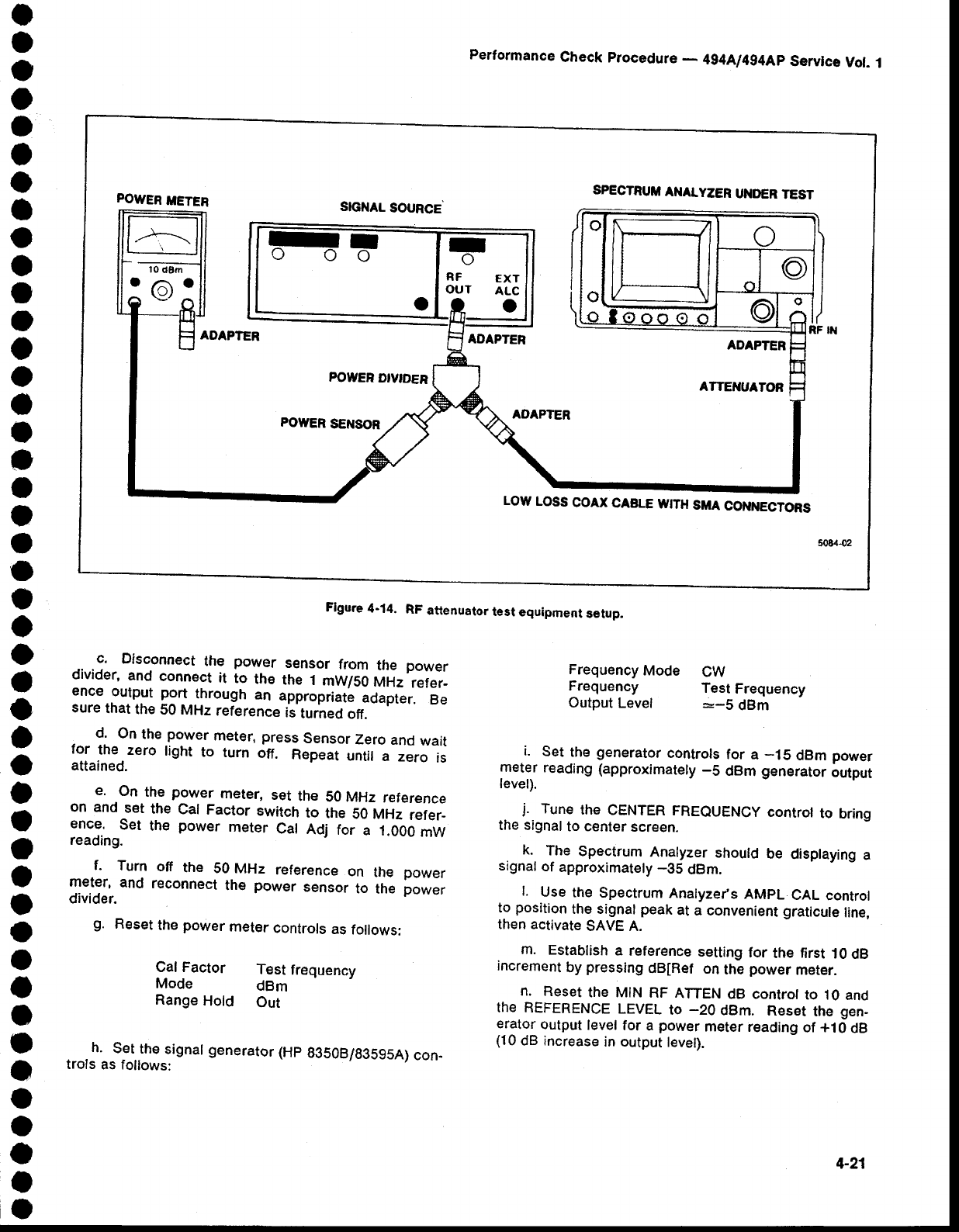
POWER
METER
SPECTRUII
ANALYZER
UI{DER
TEST
SIGI{AL
SOURCE
ADAPTER
ADAPTER
ADAPTER
ATTET'IUATOf,
FOWER
DIVTDER
POTYER
SENSOR
AOAPTER
LOW
LOSS
COAX
CABLE
IYITH
SMA
COI{NECTORS
RF
ExT
OUT
ALc
Flgure
4-14.
RF
attenuator
test
equipment
selup.
4-21