


a
o
a
a
a
a
o
o
a
o
o
I
o
o
a
I
)
o
o
o
o
,
o
I
o
o
t
o
I
I
I
a
o
o
o
o
o
o
o
o
a
o
I
o
GPIA
interface
circuit
on
th€
GptB
board (A56).
(Ihis
only
occurs
on
the
programmable
version.)
Before
each
transf€r,
the
microprocessor
loads
U1020
with
the
starting
address
of
the
RAM
data
and
the number
of
data
bytes
to
be
transferred.
When
the
GPIA interface
circuit
requires
data,
it
pulls
the
DMA
Request
line, pin
4
of
pl03S,
low.
This
iauses
U1O30C
to set
U1020's
Transferfiequest
input
high,
requesting
a
byte.
ln
rEturn,
the
DMA
Controller
ienOs
a
DIUA
request
to
the
processor,s
HALT
input, pulling
it
low.
This also
disables
any
maskabte
interrupt
iequest
to
tne
processor.
With
HALT
low,
the
microprocessor
com-
pletes
its
currenily
executing
Instruction
and
then
stops,
signals
that
the
bus is
avaitabte
(sets
the
BA
tine
high),
tri-states
its
data
bus, and
sets
itself
in
the
Read
stlte
(RflrV
line
high).
The BA
signal
disables
the
rnicroprocessor
address
bufrers,
U3030
and
U302S,
and
enables
DMA
Controller
access
to the
address
bus via
buffer
U1024
and
tran_
sceiver
U1015.
lt
also gives
bus
control
to
the DMA
Controller.
The
least
significant
address
lines
are
inter-
faced
to
Ul020
through
a
transceiver
because
the
pro-
cessor
uses
addresses
A0
through
A4
to address
the
setup
registers
in
the
DMA
controller.
The DMA
Controller
sets
th€ address,
VMA,
and
ReadfA/rite
(RflrV)
lines
to
caus€
the
RAM
to
plac€
the
proper
byte
on
the
data
bus.
Because
U10b0 is
an
open-collector
gate,
there is
no
conflict
between
the
microprocessor
and
the
DMA
Controller
over
the
R/W
line.
The DMA
Controiler
Transfer
Strobe
tIxSTB)
output
goes
low
giving
the
DMA
GRANT
signalto
tne
eFte
fir_
cuit
on
the
GPIB
board.
This
infoims
the
circuit
that
data is coming.
After
the
transfer
is
completed,
UlO20
raises
the HALT
line,
and
normal processor
operation
resumes.
Ground
from
the
GplB
board
connects
through
pin
2
of
P1035
as
a
signal
that
the
processor
and
GplB
boards are
connected.
lf
the
GplB
board
is
not
present,
such
as
for
test
purposesr
U10gSB
pin
12
goes
low.
This
disables
the DMA
request.
Interrupt
Processing.
The
microprocessor
uses
both
maskable
and
non-maskable
interrupts.
The
non_
rnaskable
interrupt
is
used
only
for
sensing
power-fail.
The
maskable
interrupt
is
used
to seise
circuits
requesting
service.
Although
these
interrupts
may
be
rnasked
by
the
processor,
they are
enabled
most
of
the
time.
These
interrupts
can
be requested
bv circuits
on
the
Instrument
Bus,
the
GplB
board,
the
DMA
con-
troller,
or
the
Timer.
The
instrument
firmware
contains
Theory
of
Operation
-
494A/4g4Ap
Servlce,
Vol,
I
service
routines
for
each
of
the
interrupts.
The
maskable
interrupts
are
sensed
at
the
microprocessor's
Interrupt
Request
(lRQ)
input.
Gate
u2036 sets
IRQ
low
if
it senses
any
of
the
int€rrupt
lines
low.
The
Input
port
buffer
U3O2O
places
the inter-
rupt infornation
and
swe€p
anformation
on
the data
bus.
This allows
the
microproc€ssor
to read
the
int€rrupt
status.
lf the
interupt
is
from
circuits
on
the
Instrument
Bus,
the
microprocessor
executes
a
poll
routine
to
determine
the
exact cause
of
the
interrupt.
The Instru-
ment Bus
circuits
interrupt
the microprocessor
by
pul_
ling
the
Service
Request
(SER
REO
or
SR)
tine
tow.
The microprocessor
responds
by
placing
address
FF
on
the
Instrument
Bus
and
setting
the
OATA
VALID
anct
POLL
signals
high.
This
causes
the
circuit
that
requested
service
to
pull
one of
the
data
lines
low.
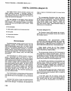
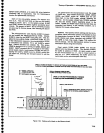
Each circuit
is
assigned
a
different
line,
as
shown
in
Table
7-22.
lt is
possible
that more
than
one circuit
requ€sts
service
at
th€ same
time.
In
that
case.
more
than
one
data line
will
be low.
The
microprocessor
reads
the
data lines
to deter_
mine
the interrupting
circuit
or
circuits.
tt
then writes
the
coresponding
bit
pattern
to the
data
bus whil€
the
address
lines
are
set
to
ZF and
DATA
VALID
and
pOLL
are
both high.
When
an interrupting
circuit
receives
a
low
on its
assigned
data line
with
the
address
lines,
DATA
VALID.
and
POLL
set as
described,
it rgsets
its
internal
interrupt
latch
and releases
the
Service Request
(sets
sER
REQ
or
SR high).
Table
7-22
POLL
BITS
0
Not Used
Not
Used
Not
Used
End of
Sweep
FREQUENCY
knob
Phase
Lock
Not
Used
Front
Panel
The
non-maskable
interrupt
signals
power
loss.
Cir-
cuitry on
the
Z-Axis
assembly
(A70)
senses
power
loss
and
sets
the
PWR
FAIL
line
low.
This causes
an inter-
rupt and starts
the microprocessor's power
fail
routine.
Wh€n
PWR
FAIL
goes
low,
e2030
turns
on and
C2030
begins
to
discharge
through
Rl032.
tf
the
tine
stays
low
until
C2030
discharges,
the RESET
line
goes
low
and
the
microprocessor
res€ts
itself.
As
part
of
its
power
fail
routing,
the microprocessor
monitors
the
PWR
FAIL, along
with
other interupts,
through
U9020.
Bit 7
Bit
6
Bit
5
Bit
4
Bit
3
Bit
2
Bit
1
7-93