


Maintenance
-
4g4A/4g4Ap
Seruice
Vot.
1
-
3.
Unplug
the CAL
OUT
coaxial
cabte
from
the
grd
Converter;
then disconnect
the
five
crt
cables
from
the
Z-Axis/RF
Interface,
High
Voltage
module,
and
Deflection
Amplifier.
4.
Looking
at
the
top
of
the instrument,
remove
the
one
screw
that
holds
th€
front
panel
to
the side
extru_
sion
between
the
crt
and
the right
side
of the
instru_
ment.
Remove
the four
screws
that
hold
the
tront
panel
to the
side
rails.
5.
Pull
the front
panel
up and
off
the
Mother
board.
Replace
the front panel
by reversing
th€ removal
procedure.
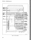
Front-Panel
Board
Removal
A replacement
Front
panel
board
comes
with switches
and
controls
for
program-
mablo
diffErent
versions
of
the
spectrum
analyzer.
Before
replacing
an
existing
board, remove
the
switches
and
controls
on
the new
board
that
are
not
used
on
the
par_
ticular
version
of
the
instrument.
1.
Remove
the front
panel
assembly
as
previously
described,
then
remove
all
the knobs.
2. Place
the front
panel
on
its face
and
remove
the
eleven
circuit
board
screws plus
the
screw
that
heat_
sinks
and
holds
U6090
on
the
board.
Note
that
the
screw
next
to
the
connector
plug
has
a
fiber
washer.
3. To
prevent
tosing
the
grounding
rings or
bush_
ings,
between
the front
panel
controls
and
the front
panel
casting,
hold
th€ circuit
board
against
the front
panel
casting
while
turning
the
complete
assembly
so it
r€sts on
the
base of
the
crt
assembly.
4.
Gently
lift
the
casting
from
the
circuit
board.
Ensure
that
the
grounding
rings
remain
on
the
shaft
of
all controls
as
the
casting
is removed.
Reverse
the r€moval procedure,
ensuring
that
the
fiber
washer
is
on
the
board
screw
next
to the connec_
tor
plug.
This
waEher
prevents
the
screw
from
shorting
a
circuit
board run
to
the front
panel
casting.
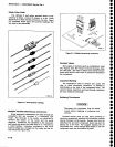
Replacing
Front
Panel
pushbutton
Switches
Removal
of
the
front panel
assembty
is
not required
to replace
any
pushbutton
switch.
The
procedure
fol_
lows:
1.
Remove
the
front panel
knobs.
Loosen and
remove
nuts and
washers
for
the
RF
lNpUT,
EXTER_
NAL
MIXER,
and
the 1st
and
2nd
LO
connectors.
2.
Remove
the screw
under the
CENTER
FRE_
QUENCY
tuning
knob
that holds
the
panel
to
the
front
panel
casting.
3. Loosen
the
black
screws
through the
crt
bezel
so
the
panel
can
be moved enough
to
lift
it off
the
cast-
ing.
4.
Unplug
and
replace
the desired
switches.
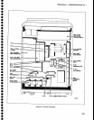
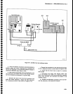
Main
Power
To
avoid
damage
to the
Mother
board con-
nector
J5041 and lnterface
connector
J1034, during
removal
or installation of
the
Power
Supply module,
use
the
following
procedure.
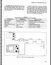
1. Disconnect
the
power
cord
and
remove
the
instrument cover.
2.
On
the circuit
board
side
of the instrument.
unplug
the
coaxial
cable
connector
P620 from
the Log
and
Video Amplifier
assembly.
On the RF
deck side
disconnect
th€
plug
for
the
cable
to
the
Reference
Lock
assembly,
at
the
lower
right comer
of
the
Power
Supply
module.
3.
For
programmable
instruments, remove
the
cable
clamp
for the
GPIB
interconnect
cable and
unplug P560
to the GPIB Extender
board.
4. Remove
the
three
screws
that
hold
the
power
module
to
the RF
deck flange
(bottom
right side),
then
remove
the
four
screws
that hold
the
power
supply
module
to
the side rails.
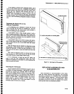
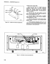
5. With the instrument
RF
deck
on
the near side,
pull
the
left side
of
the
power
module trom its
side-rail
(no
more than 1.5 inch).
Now
grasp
both
sides
of
the
module and lift
to separate
the
module from
the Mother
board.
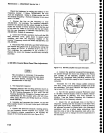
Because
C6111 and
C6101
discharge
very
slowly.
hazardous
potentials
exist
within
the
pow€r supply
for several
minutes
after
the
power
switch
is
turned off. A
relaxation
oscillator, formed
by
C5113,
R5111,
and
DS51 12, indicate
the
presence
of
voltages
in
the
circuit
until
the
potential
across
th€
filter
capacitors
is
below B0
V.
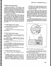
6. Loosen
and remove
the two screws that hold the
mounting bracket
for
P361
. Lift
the
cover
off
the
module
and unptug P3045
to the
Fan Drive board.
The
power
supply should
now
be
accessible.
Supply Module
Removal
[eAUloNl
o
o
o
o
o
o
o
o
o
o
o
o
o
o
o
o
o
o
o
o
o
o
o
o
o
o
o
o
o
o
o
o
o
o
o
o
o
o
o
o
o
o
o
o
6-24