


I
o
a
o
a
a
o
o
o
O
I
t
o
o
I
o
o
o
a
a
t
o
a
o
a
C
I
o
I
o
o
I
I
e
a
o
I
o
o
o
o
o
a
o
.Data
from
U4035,
the
data
buffer,
is
clocked
into
the
registers
each
time
a
difierent
tune
voltage
is
required.
U3050
feeds
the
lowest
eight
bits
to
thE
liw-order
DAC,
u2055;
U3070
teeds
the
higlgs1
eight
bits
of
the
high-
order
DAC,
U2060.
Registei
U3060ieeOs
the
remaining
bits of
both
units.
Theory
of
Operaton
-
4g4ful4g4Ap
Servlce,
Vol.
1
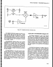
Each
side
of
the
converter
has
two DACS
summed
log€ther
to
produce
an
output
of
approximately
*10
v.
The
DACs
ar€
programmable
curreni generatois
driving
the
preamplifier-integrator
circuit.
ttre
higtr-orOer
DAd
provides
0 to 2
mA
of current
to
the circuit
via
the
buffer,
while
the
low-order
DAC
provides
approximately
+2.5
mV
at
the
inverting
input
of
the
pr€amdifier.
fn6
prearnplifier
then
drives
the integrator
via
the storage
gate.
An isolated ground
system
for
each
half
of
the
cir-
cuit
minimizes
susceptibility
to noise
and
€xtraneous
signals.
This is
because
the convefiers provide
the
dc
voltages
that
tune
the oscillators.
Track/Hold
Amptifter
.
The
amplifier
consists
of
high_order
DAC
U2O6O,
low-order
DAC
U20S5,
buffer
U2O5O,
preamptifier
Ul065,
storage
gate
01065.
and
integrator
|J21TA.
. -The
circuit
output
is required
to tung approximately
*10
V for
the fuil-scale
range
of
U2060.
ialnen
U2060
is
off
and
the
output
of
u2050
is
at
0 v,
the +10
v
out-
put
level is
set
by
1
mA
of curr€nt
through
R1055,
and
the combination
ot
R1092,
R1053,
anct R1070.
When
u2060
is fuily
on,
and
output
of
u2050 is
at
+10
v.
the
-10
V output
level
is
set
by
2 mA of
current
through
R1052,
less
the
I
mA
constanfly
flowing
in R10S5.
Full-scale gain
is
adjusted
by R1032.
Resistors
RlOS2,
R'|
053,
and
R1055
are
matched
for
temperature
coefficient
to minimize
output
voltage
drift as
a function
of
temperature.
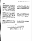
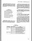
DBO
DB1
DB2
D83
DB4
DB5
DB6
DB7
Tabte
7-19
ADDRESS
70
FORMATS
Fine
Tune
low
byte
enable
Fine
Tune
middle
byte
enable
Flne
Tune
high
byte
enable
Fine
Tune
hold
Coarse
Tune
low
byts
enabfe
Coarse
Tune
middle
byte
enable
Goarse
Tune
high
byte
enable
Coarse
Tune
hold
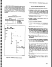
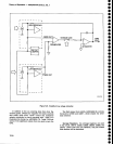
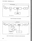
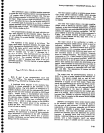
Dlgital-To-Analog
Converters.
Since
both
the
coarse
and
fine
tune
circuits
operate
similarly,
only
the
coarse
tune
section
of
the
board
will
be
discussed
here.
Figure
7-26
is
a
functional
block
diagram
of
the circuit.
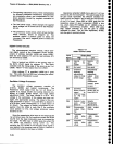
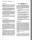
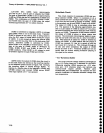
Tabte
Z-20
DAC
TUNING
CODES
Polnt
Positive
full
range
Mid-range
Negative
full-range
Results
Enables
all latches,
track
mode
Loads
zeros
into
all
positions
of
both DACs
Enables
all
latches,
track
mode
Loads
zeros
into
all
positions
of
both DACs
Enables
high
byte latch,
track mode
Loads
80
into DACs.
Midrange
value
Enables
all
latches,
track
mode
Loads
FF into
all
positions
of
both DACS
7-75