


E
-Otr
.rr
t.Eq'
i5tr
TI
-t
--
..4
-r
-tt
-
{
-ll
^rla
trl
'l
''t
I'
r'
ss603it
o
o
o
t
O
o
a
o
o
a
o
a
O
o
t
O
a
o
a
a
O
o
o
o
a
o
o
o
a
o
I
o
o
o
o
o
t
t
a
o
o
o
I
o
Performance
Check
procedure
-
4g4AJ4g4Ap
Servlce
Vol.
1
i.
Reset
the
REF
LEVEL
for
tho
best
marker
definirion,
and
the
CENTER
FREouENcy
t"
ariln
ii.,e
ryt9rs
so
span/div
accuracy
can
be
checked
ilr
the
50
MHz/div.
j.
Reset
CENTER
FREOUENCY
to 100
MHz
and
SPAN/D|V
to 20 MHz,
and
apply
50 ns
(20
frlHzy
maif<-
ers.
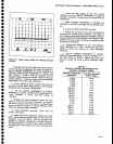
k.
check the
20
MHz
spAN/DlV
accuracy.
l.
Repeat
the
procedure
and
check
th€
SPAN/D|V
accuracy
from
10
MHz
down
to
200
kHz.
Use
faOte
q-S
as
a
guide
to
relate
time
markers
to
spAN/Dlv
settings.
Reduce
RESOLUTION
BANDWIDTH
and
CENTER
FR]E.
OUENCY
as each
setting
is
checked
to
maintain
marker
amplitude
and
definition.
_ -
rn.
Change
th€ T|ME/D|V
to
0.5 s
and
RESOLU_
TION
BANDWTDTH
to
1kHz.
Repeat
the
above
pro_
cedure
to check
the 100
kHz
to 10 kHz
SpANfDtV
selections.
N.
SEt thE
CENTER
FREQUENCY
tO
'IOO
KHZ,
RESOLUTTON
BANDWTDTH
to
100
Hz,
T|ME/DIV
to.t s
and
REF
LEVEL
to
0 dBm.
Repeat
the
above pro-
cedure
to check
the
S
kHz
to 20
Hz
SpAN/D|V
selec_
tions,
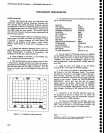
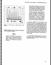
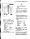
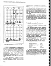
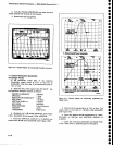
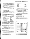
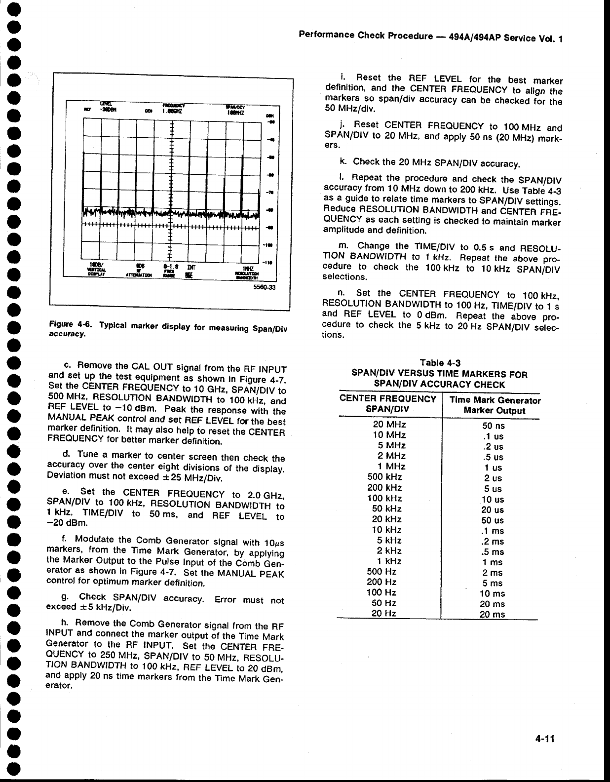
Figure
4S.
Typical
marker
dlsplay
for
measuring
Span/Div
accutacy.
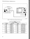
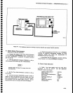
c.
Remove
the
CAL
OUT
signat
from
the
RF
tNpUT
and
set
up
the
test
equipment
;s
shown
in
Figure
4_7.
set
the CENTER
FREOUENCy
to 10
eni,
bnlr.rTDtv
to
500 MHz,
RESOLUTTON
BANDWIDTH
to'100
kHz,
and
REF
LEVEL
to
-10
dBm.
peak
the
response
with
the
MANUAL
pEAK
controt
and
set
REF
LE'EL
for
the
best
marker
definition.
lt
may
also
help
to reset
the
CENTER
FREQUENCY
for
b€tter
marker
definition.
d.
Tune
a
marker
to center
screen
then
check
the
accuracy
over
the
center
eight
divisions
of
the
display,
Deviation
must
not
exceed
*25
MHz/Div.
E.
SEt
thE
CENTER
FREOUENCY
tO 2.0
GHZ,
SPAN/DIV
to 100
kHz,
RESOLUION
BANDWTDTH
to
1
If.,
T|ME/D|V
to
50 ms,
and
REF
LEVEL
to
-20
dBm.
f.
Modulate
the
Comb
Generator
signal
with
1Ops
markers,
from
the Time
Mark
Generato-r,
by applying
the
Marker
Output
to
the
pulse
Input
of
tte
iomU
denl
erator.as
shown
in
Figure
4-7.
S;t
the MANUAL
pEAK
control
tor
optirnum
marker
definition.
g.
.
C[e9k
SPAN/D|V
accuracy.
Error
must
not
exceed
*5
kHz/Div.
h.
Remove
the
Comb
Generator
signal
from
the
RF
INPUT
and
connect
the
marker
output
6t
the
Time
Mark
Generator
to
the RF
tNpUT.
Sei
tne
CENTER
FRE-
OIENCY
to
2s0
MHz,
SpAN/D|V
to
50
MHz,
RESOLU-
NON
BANDWIDTH
to
1oo kHz,
REF
LEVEL
to 20
dBm,
and
apply
20
ns
time
markers
from
the
Time
Mark
Gen_
erator.
Tabte
4-3
SPAN/DrV
VERSUS
T|ME
MARKERS
FOR
SPANiD|V
ACCURACY
CHECK
CENTER
FREQUENCY
sPAN/DrV
Tlme
Mark
Generator
Marker
Output
20
MHz
10 MHz
5
MHz
2 MHz
1 MHz
500
kHz
200
kHz
100
kHz
50 kHz
20
kHz
10
kHz
5 kHz
2kHz
1 kHz
500 Hz
200 Hz
100 Hz
50 Hz
50
ns
.1
us
.2
us
.5
us
1us
2us
5us
10
us
20
us
50 us
.1 ms
.2 ms
.5 ms
1ms
2ms
5ms
10
ms
20
ms
Hz
4-11