


o
I
a
o
o
o
o
o
o
a
o
I
o
o
I
I
,
o
I
o
I
a
o
o
a
a
a
o
a
o
O
a
I
o
o
t
I
t
o
o
O
a
I
o
..
q:
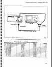
19.gt
the
Spectrum
Analyzer
RF
attenuator
set-
ting
to
60
dB,
and
increase
the reference
level
setting
by
t0
dB.
.r, lheck
that
t,€
{itEreqce
between
the
SAVE
A
and.
VIEW
g.gi.prqfr
is \ss
t\"n
s.ri
o-e.
Make
a
note
of
th€
levet
differe(rce
OetNqer/ttre
SnVe
n'anO
V|EW
B
displays.
\
s.
Using
the
data
noted
in
step
o of
part
l,
steps
n
and
o
of
part
ll,
and
step
r
of
part
ttt,
ctreck
that
devia-
tlon
over
the
entire
60
dB
range
is
less
it
"n'O
Og.
18.
Check
lF
Gain
Accuracy
(+0.2.dB/dB
Step
to
a
miximum
of
*0.S
dB/g
dB
except
at
the
decade
transitions
of
_19
Oem
to
_eO
dBm,
-29
dBm
to
__30
dBm,
_3s
oam
to
_40
dBm,
-49
dBm
ro
-S0
dBm,
and
_59
dBm
io
_60
oBm
where
an
additional
O.S
dB
can
occur
foi
a
totat
of
t
dB/decade.
Maximum
deviation
over
the
full
g7
dB
range
is
within
+2
dB)
..
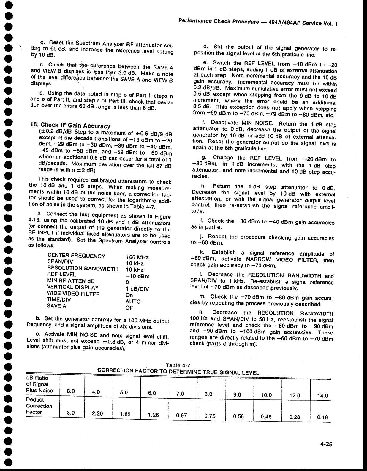
T.hf".check
requires
calibrated
attenuators
to
check
the
10dB
and
1
dB
steps.
When
mafing
measure-
ments
within
10
dB of
the
noise
floor,
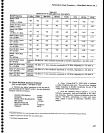
a correction
fac-
tor
should
be
used
to
correct
for
the
logarithmic
addi-
tion
of noise
in
the system,
as
shown
in
fi6te
+-2.
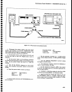
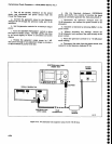
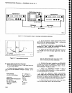
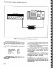
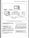
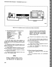
a.
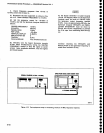
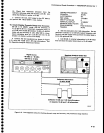
Connect
th€
test
equipment
as
shown
in
Figure
4-13,
using
the calibrated'1d
dB
ano
t
ae
attenuators
!"j ::g^::l
the
output
-of
the
g"n"r"to,
oirecily
to
the
RF
TNPUT
if
individuat
fixed
atGnu"tor"
"r"1o
be
used
as
lhe
standard).
Set
th€
Spectrum
Analyzer
controls
as
follows:
Performance
Check
procedura
-
4g4Al4g4Ap
Servlce
Vol.
1
d.
Set
the
output
of
the
signal generator
to
re-
position
the
signal
level
at
the
6th
graticule
line.
e.
switch
ihe
REF
LEVEL
from
_10dBm
to
_20
dBm in
I
dB
steps,
adding
.l
dB
of
externat
att€nuation
at
each
step.
Note
incremental
accuracy
and
the 10
dB
91n.jr9g!racy.
Incrementat
accuracy
must
be within
0.2
dB/dB.
Maximum
cumulative
erroi
rnust
not
exceed
0.5
dB
except
when
stepping
frorn
the
g
dB
to 10
dB
increment,
where
the error
could
be an
addational
0.5
dB.
This
exception_does
not apply
when
stepping
from
-69
dBm
to
_70
dBm,
_79
dBm
to
_go
oem,
itc.-
f. Deactivate
MtN
NolsE.
Return
the
1
dB step
attenuator
to 0
dB,
decrease
the
output
of
the
sign;l
generator
by 10
dB or
add
l0
dB
of
external
attenua-
tion.
Reset
the
generator
output
so
the
signal
tevet
is
again
at
the
6th
graticule
line.
-9.
change
the REF
LEVEL
from
_20
dBm
to
-30
dBm,
in 1
dB
increments,
with
the 1
dB
stef
attenuator,
and
note
incremental
and 10
dB
step
accu-
racies.
h.
Return
the 1
dB
step
attenuator
to
0 clB.
Decrease
the
signal
level
by
10
dB with
external
attenuation,
or
with
the
signat generator
output
fevel
control,
then
re-estabtish
the
signal
reference
ampli_
tude.
i.
Check
the
-30
dBm
to
-40
dBm
gain
accuracies
as in
part
e.
j.
Repeat
the
procedure
checking
gain
accuracies
to
-60
dBm.
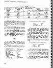
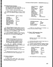
CENTEB
FREOUENCY
SPANIDtV
RESOLUTION
BANDWIDTH
REF
LEVEL
MIN
RF
ATTEN
dB
VERTICAL
DISPLAY
WIDE
VIDEO
FILTER
TrME/DtV
SAVE
A
100
MHz
10
kHz
10
kHz
-10
dBm
0
1
dB/Dlv
On
AUTO
off
k.
Establish
a signal
reference
-60
dBm,
activate
NARROW
VTOEO
check gain
accuracy
to
-70
dBm.
amplitude
of
FILTER,
then
-
b.
Set
the
generator
controls
for
a
100
MHz
output
frequency,
and
a
signal
amplitude
ot
six
Oivisions.
c.
Activate
MIN
NOISE
and
note
signal
level
shift.
Level
shift
must
not
exceed
*0.g
dB, o-,
+
minor
Oiui_
sions
(attenuator
plus
gain
accuracies).
I. Decrease
the RESOLUTION
BANDWIDTH
and
SPAN/DIV
to 1
kHz.
Re-establish
a
signal
reference
level
of
-70
dBm
as
described
previously.
m.
Check
the
-70
dBm
to
-90
dBm
gain
accura-
cies
by
repeating
the
process
previously
deicribed.
n.
Decrease
the
RESOLUTTON
BANDWTDTH
100 Hz
and
SpAN/DIV
to
50 Hz,
reestabtish
the signal
reference
level
and
check
the
-g0
dBm
to
_gO
dBm
and
-90dBm
to
-1
00dBm
gain
accuracies.
These
ranges
are
directly
related
to
the
-60
dBm
to
_70
dBm
check (parts
d
through
m).
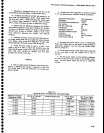
CORRECTION
FACTOR
TO
DETERMINE
TRUE
STGNAL
LEVEL
Table
4-7
dB
Ratio
of
Signal
Plus
Noise
3.0
4.0
5.0
6.0
7.0
8.0
9.0
10.0
't2.0
14.0
Correction
Factor
3.0
2.20
1.65
1.26
0.97
0.75
0.s8
0.46
4.28
0.18
4-25