


Theory
of
Operation
-
4g4A/494Ap
Servlce,
Vol.
1
o
o
O
o
o
o
o
o
o
O
o
o
o
o
o
o
o
o
o
O
o
o
o
o
o
o
o
o
o
o
a
o
O
o
o
o
o
o
o
o
o
o
o
o
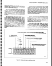
POWER
SUppLy
(Diagram
10)
The
Main
power
Supply
furnishes
all
the
regulated
voltages
for
the
spectrum
analyzer,
exc€pt
the crt
high-
voltage
:uppty.
The
high-efficiency
desiin
of
the
Main
Power
Supply
reduces
total
weight
ind
conserves
en_ergy.
The
power
supply
circuits
lre
divided
into
th€
primary
circuits
and
the
iecondary
and
fan
drive
cir-
cuits.
primary
Circuits
(Diagram
46)
. .ft"
power
supply
primary
circuits
consist
of
the
fol_
rowing:
the
rine
input
circuit,
wnicn
rectifies
and
firters
the incoming
line
voltage;
and
the inverter,
which
drives
the
primary
of
the
power
transformer.
Line
Input
Circuits
_^
Power
is
applied
through
tine
filter
FLg0l
,
line
Fuse
F301,
.
and
through
FLgb2
(for
additional
normal
mode/common
mode
EMt
fittering)
to POWER
switch
5300.
The
power
is
then
sent
thro-ugh
line
s€lector
con-
nector
J1091.
The
line
filter
plevents
power-line
interference
from
entering
the
power
supply,
and
it also
prevents
internally-generated
signals
from
radiating
out
the
power
cord.
Line
selector
switch
S302
allows
instrument
opera_
tion
trom
€ither
a
lSV
nominal
or
230V
nominal
line
voltage
sourcg.
With
S3O2
is
in
the
115
V
position,
pins
1 and
2 of
p1091
are
connected
to
the
input power,
and
rectifi€rs
CR3096
and.
CR4094
operate'in
ionjunction
with
energy
storage
filter
capacitors
C6101
and
C6111
as
a
full-wave
doubleq
thus,
the
voltage
across
the
two
9lqacllol:
is
the
peak_to_peak
vatue
oJ
the
line
vottage.
With
S302 in
the
290
V
position,
pins
2
and
3 of
p1091
are
connected
to the
input powerand
CR3096,
CR4O95,
CR3098,
and
CR4094
operate
as
a
bridge
rectifier.
As
a-
result,
the
output
voltage
appliecl
to
the inverter
is
about
the same
for
1lS
V or
23b-V
operation.
Because
G6011
and
C610.t
discharge
very
slowly,
hazardous
potentials
exist
wiihin
tne
power
supply
for
several
minutes
after
the
POWER
switch
is
turned
off.
A relaxation
oscillator
formed
by
C51 lg,
R5l
11,
and
DS51
12,
indicates
the presence
of
voltages
in
the
circuit
until
the
potential
across
ihe
filtor
capacitors
is
below
g0
V.
Thermistors
RT209g
and
RT2097
limit
current
surge
at
turn on.
After
the instrument
warms
up,
the
current
demand
drops.
The
increase
in
temperature
decreases
the resistance
value
of
the
thermistors
so
they
have
minimum
affect
on
the circuit.
Thermal
cutout
switch
S2109
opens
if
thE interior
of
the instrurnent
reaches
109"C
to
prevent
overheating
in
case
the cooling
fan
fails.
E1094
and
E2095
are
surge
voltage
protectors.
When
the line
selector
switch
is
in
the
115
V
position,
only
E1094
is connected
across
the
line
input.
it
a
peak
voltage
surge
in
€xcess
of 230
V
occuis
across
the
input,
or
if
the
instrument
is
accidentally
connected
to a
230
V source,
E1094
will
break
down
and
demand
enough
current
to
open
the
line
fuse.
When
the
instru-
ment
is
operated
with
the
line
selector
at
230v,
E1094
and
E2095
operate
in series
to
protect
the
input
against
line
surges
of approximately
460
V
peak.
,
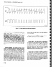
The
voltage
for
the line
trigger
is
taken
across
CR3096.
This
48
Hz
to 440
Hz
vottage
drives
optical
isolator
U5043. The
pulsating
5
V
output
is
ac coupled,
then sent
both
to
the
Sw€ep
circuit
to
provide
instru,
ment
triggering
at
ths line
frequencios
and
to th€
Z-Axis
board
for
the
Power-Fail
Detector
circuit.
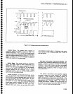
Inverter
Circuit
The inverter
consists
of
a
multivibrator
that
pro_
duces
a
rectangular
shaped
signal
to drive
the
ramp
generator
and
th€ inverter
logic
circuits.
The
ramp
gen-
erator produces
a
low-level
sawtooth
ramp
that
is
applied
to
the
primary
regulator
circuit.
The
inverter
logic
circuits
control
the
duty
cycle
of
the inverter
driver
and
the inverter
output
stage.
The
primary
regulator
circuit
compares
the +l
7
V supply
output
with
a
refer-
ence voltag€,
then
gates
the
inverter
logic
circuits
off
and
on
to control
the
inverter
duty cycle
and
the
effective
primary
voltage.
The
inverter
driver
stage
amplifies
the signal
from
the
inverter
logie
circuit
and
drives
the output
stage,
The
output
stage
consists
of
two
power
switching
transistors
that
drive the
primary
of
main
power
transformer
T4021.
The
primary
ovei-
current
sense
and soft
start
circuits
add
protection.
Multivibrator.
U6059, a
low-power
S55 tirner,
is
a
multivibrator
that operates
at
approximately
66 kHz
and
90-7-"-
duty cycle.
Oscillator
frequency
is adjusted
by
R6061.
The rectangutar-shaped
output
signat
is appliei
through
R6052
to the
primary
of
T6044
in
the
ramp
gen-
erator and
atso
directty
to
u6053,
u6063A,
u60638, and
u6069.
7-103