


o
o
o
t
I
o
o
o
o
o
a
o
O
o
a
o
O
o
o
o
o
o
o
o
o
o
I
a
o
o
a
a
o
a
o
o
a
a
a
o
o
o
a
o
Fan
Drfve
Circuit
The
fan
drive
circuit
provides
a
temperature-
con-
trolled
current
drive
to
the
fan
motor.
if,e
circuit
pro-
1y:?:
"
thr€e-phase_drive
culent
of
approximatety
240
Hz
operating
freguency.
The
actuar
ctrive
circuit
operates
as
a
ring
counter.
Transistors
Ol03g
and
e1044
form
a
vottag€
regu_
!:tlT- _c_ontrotted
by
th€rmistor
RT2O4S.
The
value
of
RT2045
varies
inversely
with
tf,"
int"in"i
temperature
of
the anatyzer.
The
therinistor
and
,".Gioi
nzo+2
fix
the
turn-on
voltage
at
the
emitter
of
e1044
ai
approximatety
-13
V.
The
voltage
goes
mor€ positive
as'tire
andyzt,Jr
warms
up.
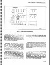
The
ring
counter
consists
of
three
stages.
Because
of
circuit
imbalances,
when
the
anrtyzer-is-nrst
powered
up one-of
the
stages
begins
to
con'duct
before
the
oth-
9r1
Tfie
stag€s
consast
of
e1025
.nJ-etOzO,
,itt
RlGlt/C1092
and
RtOzZClOle
as-
ine'
trequency-
99t^"ITjli.nS_-components;
e2025
anO-'-btOtg,
with
R1033/C1033
and
R2Ot9/Ct01g
as
the
frequency_
$t^"Tjl'lg,components;
and
e2030
"nO-OZOZO,
*itt
R20141C2012
and
R2016/C2O18
as
ite
rrequency-
determining
components.
Theory
of
Operation
-
4gtA/4g4Ap
Servlce,
Vot.
1
Assume
that
the
stage
with
e1025
anct
e1020
begins
to conduct
first.
The
collector
vottage
of
e1025
is
near
-1T
V,
which
fixes
that
point
as
the
most
nega-
!y"-^rl _a_
rlng
consisting
ot
itrOgz,
R1029,
niOig,
R2036,
R2034,
and
RiO36.
Since
the
emi*er
vottage
of
the
three
control
transistors
(Of
O2O,
el01g,
anO
OiOeO;
is
the same,
the
voltage
division
around
ihe resistive
ring
is such
that
el0lg
and
e2020
remain
cut
ofi.
{he1
the capacitive
charge
that
hotds
etO2O
in
con-
duction
bleeds
off,
the
transistor
cuts
off
and
th€
next
stage
can
begin
to
conduct.
Operation
of
the
other
two
s.!ag,es
is
prevented
until
the
RC
cornbination
discharges.
The
fan
motor
inductance
works
in
con-
junction
with
the
RC
components
to
regulate
the switch_
ing
of
the stages.
This ring-counter
action
builds
up slowly
until
the
circuit
produces
a
three-phase
drive
signat
of
approxi-
mat€fy
240
Hz.
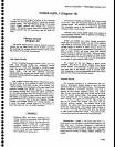
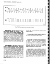
Th€
inductance
of
the
m-otor
coils
iound
off
the othenrvise
sharp
comers
of
the
drive
signal;
so,
the current
waveform
al
p2O2O
pins
1,
2, and
3 looks
s-imilar
to
the
output
of a
half-wave
rectiher.
The
fan
drive
signals
are phased
approximately
120
degrees
apart.
7-107