


Diagnostic
Firmware
The
firmware
in
the
sp€ctrum
analyzer
provldes
diagnostic
routines
that can
be
used
wittr
itre Diagnostic
part
of
this
section
to
troubl€shoot
th€ Frequency
Con-
trol system
and
diagnose
power
Supply
problems.
This
part
fottows
GenErat
trouOtestrbttini
information.
Refer
to this
part
to
help
isolate
probljms
within
this
!9op.
Th9
foilowing
are
atso
some g€nerat
suggestions
that
may
help
isolate
a
problem
when
troubleshooting.
Troubleshooting
Steps
1. Ensure
that the
problem
exists
in
the spectrum
analyzer
by checking
the
operation
of
associaied
test
equipment.
2. Try
to isolate
the
problem
to a circuit
or at
l€ast
board
level
by
evaluating
operationaf
symptoms;
for
example,
absence
of
the fr€quency
dot coutO
be caused
by
a
malfunction
in
the video
summing
stage,
the
marker
generator,
or
switching
circuits.
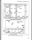
3. Three
levels
of
block
diagrams
are
provided
to
aid
in understanding
the
theory
of
operation.
The
most
detailed
level
is
adiacent
to
the
schematic
and
usually
provides
signal
and
voltage
tevels
at critical pointi
within
the circuits.
Signal levels
are
usually
the
ievels
required
to
produce
full
screen
deflEction.
4. lnstructions
on
how
to
remov€
or
replace
those
assemblies
which
are
not
obvious,
are
provided
in
this
section.
Refer
to
this
part
before
removing
any
assem_
bly for
testing
or repairing.
Matntenance
-
494A,1494Ap
Service
Vot.
1
_ _
5.
Visually
inspect
the area
or
assembly
for
such
defects
as
broken
or
loose
connections,
improperty
connected
components,
overheated
or
burned
com_
ponents,
chafed
insulation,
etc.
Repair
or
replace
all
obvious
defects.
In
the
case
of overheated
com_
ponents,
try to
deterrnine
the
cause
of
the
overheated
condition
and correct
before
applying
power.
6.
Use
successive
electrical
checks
to
try
to
locate
the
problem.
An oscilloscope
is a
valuable
t€st
item
for
evaluating
circuit
performance.
lf appticable,
check
the
ca-libration
adiustments;
howEver,
before
changing
an
adjustment
note its
position
so it
can
be retumed
tb its
original
setting.
This will
facilitate
recalibration
after
the
trouble
has
been located
and repaired.
7.
Dotermine
the
extent
of
the
repair
needed;
if
complex,
we
recommend
contacting your
local
Tek_
tronix
Field
Office or repres€ntative.
lf
minor.
such
as
a
component
replacement,
see
the Replaceable
parts
list
for
replacement
information.
Removal
and
replacement
procedure
of
the
assemblies
and
sub-assemblies
are
described
under
Corrective
Maintenanc€.
When
measuring
voltages
and
waveforms,
use
extr€me
care
with
the
placement
of
test
probes.
Because
some
circuit
boards
have
a
high component
density, access
to
points
in
some circuits
is
limited.
A
test
prob€
could accidentally
short
a circuit
and
gen-
erate
transient voltages
that
can
destroy
many static-sensitive
components.
DIAGNOSTICS
This
part
consists
of
explanations
and
procedures
for
troubleshooting
the freguency
control
system
and
the
power
supply
using
diagnostic
firmware
in
the spec_
trum analyzer.
TROUBLESHOOTING
USING
THE ERROR
MESSAGE
DISPLAY
Introduction
This
part
contains
procedures
for
troubleshooting
the frequency
control
system
and
thE
power
supply.
When
th€
microprocessor
detects a failure
or error
in
the Frequency
Control
loops or a failure
in
the
power
Supply
voltages
it will
cause
the
spectrum
analyzer
to
display
an
error message
near center
screen
for a few
seconds;
this is followed
by an error status
message
near
th€
top
of
the screen
whieh rernains
as long as
the
error
or
problern
exists.
These
error
messages
pertain
to
problems
that
exist
under current
instrument
operational
modes or
front
panel
settings; for
example,
an error
that
pertains
to the
hardware in
the
phase
lock loop
will
exist only
when
thE instrument
is
in the
phase
lock
mode
(nar-
rower
span/div settings).
6-5