


Adiustment
Procedure
-
494A/tg4Ap
Service
Vol. 1
(3)
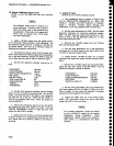
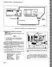
Connect the counter
to
Tp2o11
on
th€ con-
trolled
Oscillator
board (Figure
5-26a)
and atter-
nately
press
AUTO
RESOLN
and
IDENT
and
check
for a
count reading
of either
25.0g4g
MHz or
25.0328
MHz.
f.
Chec-k
Opera0on of
Strobe
Drlver
The
*Phase
Lock
Synthesiz€r"
test is
still
used
for
this
test. lf aborted,
press
<Blue-SHtFT>
PULSE
STRETCHER
to
return
to
the
Synthesizer routine.
Any
step in
the routine
willwork.
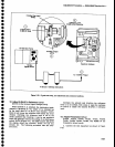
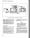
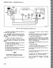
(1)
Connect the
test osciltoscope
to Tp2015
on
the
Strobe
Driver
board
(Figure
5..26b)
and
eheck
for a
square
wave response
with
a
Time/Div
setting of
.05
ps.
Amplitude
should
be
==5
V
peak-to-peak.
(21
Connect the
test osciiloscope
to Tp2Og7 and
check
for a sinusoidal
waveform
of
approximatety
5vpp.
(3)
lf
the amplitude
of
the
strob€ signat
is
low
and
noisy, chang€
the values
of select capacitors
Cl01 6,
C1018,
C1032,
and
C1034
for maximum
amptitude
and
minimum noise
at
TP2087. The
range
of values
for
these
capacitors
is
3.3
pF-27 pF.
(4)
Connect th€ counter
to TP2087 and
check for a
count of either
5.018868
or
5.00642
MHz.
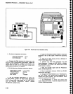
(5)
Gonnect the
test oscilloscope
to
JS04
and
check
for5Vlogiclevels.
(6)
Press <Blue-SHIFT>
to abort the
test.
g.
Error Ampllfier
-
This
procedure
sets
loop
gain
which
is required
when
either
the
Phase
Lock assembly,
1st
LO, Phase
Detector,
or
Error
Amplifier is
replaced.
(1)
Set
SPAN/DIV
to 200
kHz then
press
<Btue-
SHIFT> PULSE
STRETCHER.
The
DTAGNOSTTC
FUNCTIONS
menu
will
now be disptayed.
Setect
menu
item
3
(DIAGNOST|C
A|DS)
and
setect
t
st LO
PHASE
LOCK
(sub-menu
item
0).
phase
tock
should
bs disabled.
(2)
Connect the
test osciiloscope
to
Tp203B (Figure
5-26b) and set
the
test osciltoscope
Time/Div
to
20 ms.
Check for
a
waveform
with
an amplitude
that is approximately
6 V
peak-to-peak.
(3)
Press
lOdBiDlV
to enable
phase
lock
and note
that
the message
indicates
LOCK ENABLED.
Con-
nect the test oscilloscope
to
Tp
3081
(Figure
5-26b)
and
vary
R3082 from
stop
to
stop
and
note
that the
beat
note signal
varies
in amplitude.
Press
<Blue-
SHIFT>
to
return
to normal
op€ration.
(4)
Set
th6
TIME/DIV
to AUTO,
FREOUENCY
RANGE
to 1.7-5.5 (Band
2), and
SpAN/D|V to
50
kHz.
(5)
Remove
P3057
(Figure
5-26b). This
turns on
the
strobe
to the Phase
Gate.
Set
Loop Gain
R3082
fully
counterclockwise. Move
P2035 to
pins
2 and
3.
(6)
Monitor TP3081 with
the
test
oscllloscope.
Trigger
the test
oscilloscope externally with
the
sig-
nal
at TP2037
(U204&6)
shown
Figure
5F26b.
Set
the
test
oscilloscope Time/Div
to 5
ms
and
Volts/Div
to
0.5 v. Note
the
beat notes. Beat
notes
are
pro-
duced
by
the difference
betw€en strobes from
the
phase
lock
(one
every 5 MHz) and
th€
particular
fre-
quency
the
lst
LO
is
tuned to.
O)
Vary
R3082 clockwise
slowly
and
make
a note
of
th€
amplitude
of
the
beat
notes
prior
to lock
The
beat
not€s
will
dasappsar
when
lock
is achieved.
(8)
Set R3082 fully
clockwise.
Reset
SPAN/DIV
to
MAX, RESOLUTTON
BANDWIDTH
to
100 Hz,
and
TIME/olv
to
AUTO. D€activate
vlEW
A and
VIEW
B.
(9)
As
the
sweep
scans across
the
span,
note
the
position
of the
smallest
beat note.
Tune
the
CENTER
FREQUENCY to
position
the
fr€quency
dot
at this location, then
reduce
the
sPAN/Dlv
to
100 MHz.
Set
TIME/DIV to
1 s and activate VIEW
A.
(10)
Adjust R3082 to
set
the
amplitude of
the beat
note to
1.5x
the
amplitude
noted
in
sub-part
7 of
part
g.
(11)
Reset the TIME/DIV to
MNL,
and
deactivate
VIEW
A.
Set SPAN/DIV
to 50 kHz,
then increase
it
to
100
kHz. Center
th€
crt
beam
with MANUAL
scAN
control.
set
the oENTER/MARKER
FRE-
OUENCY
control lor
a null
of
the display
on
the test
oscilloscope.
(12)
Position
the
crt beam
with
the
MANUAL
SCAN
control
4
divisions
from center screen
(400
kHz from
c€nter
screen).
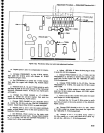
(13)
Monitor TP1031
on
the
Error
Amplifier
board
with
the test
oscilloscope.
Externally trigger the test
oscilloscope
with the
signal at TP1031. Set
R1061
to
midrange.
(14) Vary Rl061
clockwise
until the
oscilloscope
display
just
starts to
break
up.
(15)
Use the
MANUAL SCAN
control
to
position
the
beam
4 divisions
on
the
opposite side of center
screen. As the beam
crosses center
screen,
the
display
on
the test
oscilloscope should
go
through
a
null. lf no nufl
occurs as the beam
reaches center
scre€n,
reset
the
CENTER/MARKER
FREQUENCY
control for
a null
of
the display
on the test
oscillo-
scope.
(16)
Adjust R1061
such
that break
points
are
400
kHz on either
side
of center
screen.
o
o
o
o
o
o
o
I
a
o
o
t
I
a
t
I
a
,
o
o
I
I
a
o
I
o
o
a
o
o
o
o
t
o
I
o
o
o
I
o
o
a
o
o
5-28