


Performance
Check
procedure
_
4g4Al4g4Ap
Service
Vol.
1
14.
Check
Frequency
Response
(Response,
about
the
midpoint
between
two
€xtremes,
measured
with
10
dB of
RF
attenuation
and peaking
optimized
in
the applicabl€
bands
for
each
center
frequency
setting,
is
as
follows:
Band
1: +1.5
dB
from
10
kHz
to 1.g
GHz
Band
2:
*2.5
dB
from
1.7
to
S.5
GHz
Band
3: r2.S
dB from
3
to
7.1
GHz
Band
4:
i3.S
dB
from
5.4
to
1g
GHz
Band
5: iS.O
dB
from
t5
to 21
GHz)
(Response
with
respect
to
100 MHz
is
as,ollows:
Band
1:
*2.5
dB
from
t0
kHz
to 1.g
GHz
Band
2: *3.5
dB
from
t.Z
to
5.5
GHz
Band
3:
*3.5
dB
from
3
to 7.1
GHz
Band
4:
*4.5
dB
from
5.4
to
1g
GHz
Band
5: *6.5
dB from
t5
to
21
GHz)
.
The
response
at
each
check point,
above
band l,
should
be
peaked
with
the
MANUAL
PEAK
controt.
^, ?:
Check
frequency
response
from
0.01
GHz
to
21
GHz
(Bands
1
through
5).
(1)
Connect
the
CAL
OUT
signat
to the
RF
tNpUT,
and perforrn
the
<Blue-SHIFT>
CAL
routine.
(2)
Set
the
Spectrum
Analyzer
controls
as
follows:
CENTER
FREQUENCY
1OO
MHz
SPAN/D|V
500
kHz
RESOLUTION
3 MHz
REF
LEVEL
-20
dBm
VERTICAL
DTSPLAY
2 dB/Dtv
MIN
RF
ATTEN
dB
O
TIME/DIV
AUTO
00)
D€activate
MAX
HOLD,
and
repeat
parts
6
through
10
for
a CENTER
FREQUENCy
of
1.5
GHz
(1
GHz
to 1.8
GHz).
(1
1)
Calculate
the
hatfway
point
between
the
highest
and
the lowest peak
from
the
peak
data
noted
in
parts
g
and
10.
(12)
Check
that
swept
frequency
flatness
is
within
11.5
dB in Band
1.
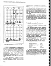
(13)
Switch
the
Spectrum
Analyzer
to Band
2
(<Blue-SHIFT>
BANDA),
CENTER
FREeUENCy
to
2.7 GHz,
and
SPAN/DIV
to 200
MHz.
(14)
Reset
the sweep
oscillator
controls
for
a
sweep
output
trom 1.7
GHz-3.7
GHz.
Enable
sin-
gle
sweep
on
the
sweep
oscillator.
Before
sweeping
any
range
in Bands
2
through
5, set
th€
CENTER
FREQUENCy
to
the center
of
the
range;
apply
a
cw
signal
at
this center
frequency;
and
peak
the
response
with
the
MANUAL
PEAK
control.
(15)
Check
that
amptitude
deviation
from
thE
'1
00
MHz
reference
does
not
exceed f3.5
dB.
(16)
Again,
make
a note
of
the highest
and
lowest
peaks
for
later
comparison.
(17)-
Check
frequency
response
in
the
range
3.7
GHz-5.5
GHz
(CENTER
FREQUENCY
Lt
4.6
GHz and
SPAN/D|V
at
200
MHz).
Continue
making
notes
of
the
highest
and
lowest
peaks
for
comparison
later
on.
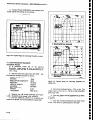
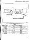
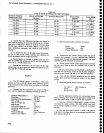
(18)
Check
Bands
3
through
5 according
to
Tabte
44.
8e sure
to
make a
note
of the
highest
and
lowest
peaks
after each
check.
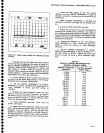
(19)
Calculate
the
halfway
point
between
the
highest
and
the lowest
peak
from
the
peak
data
noted in
parts
16
and17.
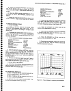
(20)
Check
that swept frequency
flatness
is
within
*2.5
dB in
Band
2
and
Band
3, within
*3.5
dB in
Band 4,
and
within *5.0
clB in
Band
5.
lf
any
segment
or
portion
of
the
span
fails
to meet
the
specification,
set
the FRE-
QUENCY
to the center
of
this
portion;
apply
a
cw
marker
at this center
frequency
and
re-peak
with
the
MANUAL
or
AUTO
PEAK-
lNG.
Decrease
the
FREQUENCY
SPAN/D|V
to
display
that
portion
and
then recheck
the
frequency
response for
this
portion.
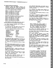
PEAK/AVERAGE
Fully
Counterclockwise
o
o
o
o
a
o
a
I
o
a
a
o
o
o
o
o
o
o
o
o
o
t
o
o
o
o
o
o
o
o
o
o
a
o
o
O
o
o
a
o
o
a
o
o
(3)
Set
the
CAL AMPL
adjustment
for
5 divisions
on
the
Spectrum
Analyzer
diiptay.
This
is
the
1OO MHz
reference.
Activate
SAVE
A
to
save
the reference.
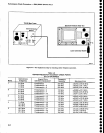
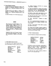
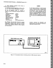
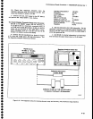
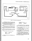
(4)
Connect
th€
test
equipment
as
shown
in
Figure
4-11.
(5)
Set
the
sweep
oscillator
controls
for
a
cw
output
that
rnatches
the
SAVE
A
display
(output
frequency
of
100
MHz
and
an
output
amptituOi
of
approxi-
mately
-20
dBm).
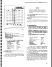
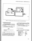
(6)
Deactivate
SAVE
A.
Reset
the
CENTER
FRE-
QUENCY
to 500
MHz,
and
SpANiDtv
to 100
MHz,
and
activate
MAX
HOLD.
(/)
R:seJ
the sweep
oscillator
controls
for
a
sweep
output
from
0.01
GHz-1
GHz.
Enable
singlb
sweep
on
the sweep
oscillator.
(8)
Check
that
amplitude
deviation
from
the
100
MHz reference
does
not
exceed
*2.S
dB.
(9)
Make
a
note
of
the
highest
and
lowest
peaks
for
later
comparison.
4-16