


Adfustment
Procedure
-
4g4Ll4g4Ap
Servtce
Vot. 1
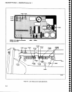
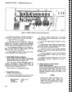
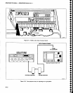
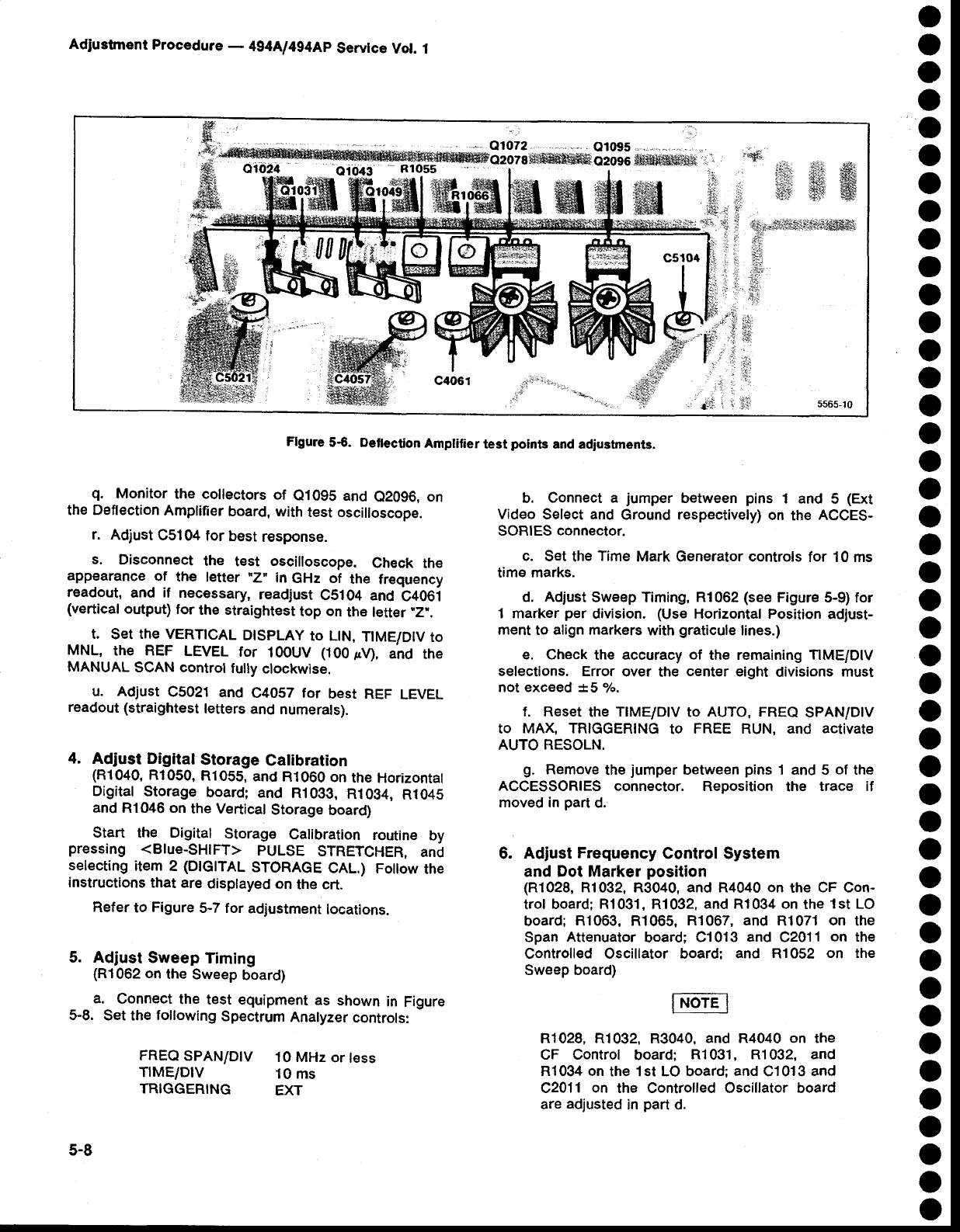
Flgure
5€. Deflection
Amptilier
test
points
and adiuetments.
o
o
o
o
o
o
o
o
o
o
o
o
o
o
o
o
o
o
o
o
o
o
o
o
o
o
o
o
o
o
o
o
O
o
o
o
o
o
o
o
o
o
o
o
q.
Monitor
the collectors
of
e1095
and
e20g6, on
the Deflection
Amplifier
board,
with
test oscilloscope.
r.
Adjust
C5104
tor
best
response.
s,
Disconnect
the
test
oscilloscope.
Check
the
appearance
of
the
letter
*Z'"
in
GHz of
the
frequency
readout,
and
if
necessaryt
readjust
CS1O4
and
C406i
(vertical
output)
for
the straightest
top
on
the
letter
"Z-.
t.
set
the vERTtcAL
DtspLAy
to LtN,
T|ME/D|V
to
MNL,
the REF
LEVEL
for
100UV
(100pV),
and
the
MANUAL
SCAN control
fully
clockwise.
u. Adjust
C5021
and
C4057
for
best REF
LEVEL
readout (straightest
leters
and
numerals).
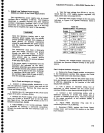
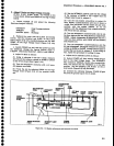
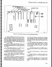
4.
Adjust Digital
Storage
Calibration
(R1040,
Rl050,
R1055,
and
R1060
on
the Horizontal
Digital
Storage
board;
and
R1033,
R1Og4,
R1045
and
R1046 on
the Vertical
Storage
board)
Start
the
Digital
Storage
Calibration
routine
by
pressing
<Blue-SHIFT>
PULSE
STRETCHER,
and
selecting
item 2
(DIGITAL
STORAGE
CAL.) Foilow
the
instructions
that ar€
displayed
on
the crt.
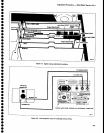
Refer
to
Figure
5-7 for
adjustment
locations.
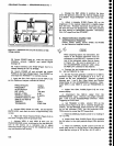
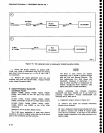
5. Adiust
Sweep
Timing
(Rl062
on
the
Sweep
board)
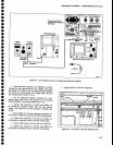
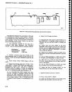
a.
Connect
the
test equipment
as
shown
in
Figure
5-8.
Set the
following
Spectrum
Analyzer
controls:
FREQ
SPAN/D|V
10 MHz
or
tess
TIME/D|V
10 ms
TRIGGERING
EXT
5-8
b.
Connect
a
jumper
between
pins
1 and
5
(Ext
Video
Select and
Ground respectivety)
on
the
ACCES-
SORIES
connector.
c.
Set
the
Tim€
Mark Generator controls
for 10 ms
timE marks.
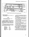
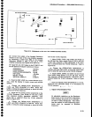
d. Adjust
Sweep Timing, Rl062
(see
Figure
5-9)
for
1 marker
per
division.
(Use
Horizontal Position
adjust-
ment
to
align markers
with
graticule
lines.)
e. Check
the accuracy
of
the remaining
TIME/DIV
selections. Error
over
the
center
eight
divisions
must
not exceed !.5
o/o.
f. R€set
the
TIME/D!v
to
AUTo, FREQ
SPAN/D|V
tO
MAX,
TRIGGERING
tO
FREE RUN, ANd
ACtiVAtE
AUTO
RESOLN.
g.
Remove
the
jumper
between
pins
1 and 5
of
the
ACCESSORIES
connector. Reposition
the
trace if
moved in
part
d.
6.
Adjust
Frequency
Control System
and Dot Marker
position
(R1028,
R1032, R3040, and R4040 on
the
CF Con-
trol
board; R1031, R1032,
and R1034 on
the
1st LO
board;
R1063, R1065, R1067,
and
R1071
on
the
Span
Attenuator
board;
C1013
and
C2011
on the
Controlled Oscillator board:
and R1052
on the
Sweep board)
R1028, R1032, R3040,
and R4040 on the
CF Control
board:
Rl031, R1032, and
R1034
on
the 1st LO board:
and
C'!013
and
C2011
on
the Controlled Oscillator board
are
adjusted
in
part
d.
{di
'
##