Tektronix"
Cdmfrittsd
to
Erca{ence
Date:2-22-88
Producl:
see
list
MANUAL
CHANGE
INFORMATION
Change Reference: M6391 1
Manual
Part
No:
see
list
product
Group:
26
I
a
I
o
o
a
o
a
o
I
o
o
o
o
a
o
o
I
)
o
o
t
a
O
o
o
a
o
a
o
I
o
o
o
o
o
a
O
o
o
o
o
t
t
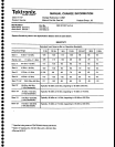
Inslrument
4941P
service 1
495/P
service 1
49?NAP
service
494AIAP
service
Manual
070-4416-00
070-5084-00
070.5565-00
070-5560-00
Efr/sN
801 1 156
8,020228
8010702
8010383
1
't
Replace
Deflection
Amplifiers
Gain
and
Freguency
Besponse
in
the
Adjustment
Procedure section
with
procedure
below.
3. Adjusl
Deflection Ampli{ier
Gain,
Frequency
Response,
and
readout
Gain and offset.
(C3080,
C3060,
C1030, C1040,
R1055, R1066,
R5020,
and
R5030
on the
Deflection
Amplifier board).
A.
Connect
the
test equipment
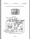
as shown in figure
5-4.
Set
the TIME/DIV
to
1 ms. Position
the
trace
on
the
bottom
gratiarle
line.
B.
Set the funclion
generator
controls
for
a 500H2 sinewave
signal,
with
an amplitude of 0 to
+ 4V.
Connect
a
jumper
between
pins
1
and
5
(Ext
Video
Select
and Ground
respectively)
on the
ACCESSO-
FIIES
connector.
Deactivate
VIEW
A
and
V|EW
B,
and sel
TRIGGERING
to
tNT.
C. Adjusl
the
Vert
Gain, R1066 (Figure
5-2)
for
a
fuil
graticute
screen disptay.
D. Disconnect
the
500H2
signallrom
the MARKERA/IDEO input. Remove
the
jumper
between
pins
1
and 5 of
the
ACCESSORTES
connector.
Reset Triggering
lo
FREE RUN.
E.
Set
TIME/DIV
to MNL.
Monitor
TP2
on
the Sweep
board
(Figure
5-2)
with
a
vollmeter
(Digital
Multime-
te4.
SET
THE
MANUAL
SCAN
controlfor
0.0
V reading
on the
voltmeler
(TP2),
Sel lhe
horizontal
POSITION
control
lo
center
the CRT beam
(dot).
F.
Reset
the MANUAL
SCAN
controtfor
a
reading
of +5V
alTpz.
G.
Adjust
Horiz
Gain,
R1055
(Figure
5-2)
to
position
the
crt beam
to the
right
gralicule
edge
(1Oth graticule
line).
H. Reset
the MANUAL
SCAN
control
such that
the crt beam
(dot)
moves lo the left
edge
ot the
graticule
and check
thal
the
voltage
at TP2 is now
-5.0V
+ or
-
0.2V.
l.
Disconnect
the vollmeter,
set
TlMgDlV
to
AUTO,
change the tesl oscilloscope
to
EXT
TBIGGER,
and
apply lhe Readout
CIf
signalat TP1038
on the
CRT
Fleadoul board
(Figure
5-5) to
the
lest
oscillosmpe
Ext
Trigger
input.
Set the
test oscilloscope
Time/Div
to 2us.
Page 1
ol 5


