


I
o
o
t
o
I
o
I
o
t
I
o
o
I
a
I
o
o
o
o
I
o
o
o
o
O
t
e
t
c
o
o
o
o
o
o
o
I
o
o
o
I
t
3
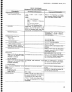
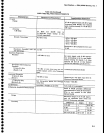
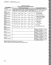
Characteristic
RF INPUT
lmpedance
VSWR
with
10
dB or
more
RF
Attenuation
10
kHz-2.5
GHz
2.5-6.0
GHz
6.0-18
GHz
18-21
GHz
VSWR
with
0
dB
RF
Attenuation
10 kHz-2.5
GHz
2.5-6.0
GHz
6.0-18
GHz
18-21
GHz
Maximum
Safe Input
With
0 dB
RF attenuation)
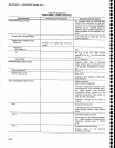
1
dB
Compression
point
(Minimum)
Bands
1-5
(10
kHz-21
GHz)
EXTERNAL
MIXER
EXT
REF
IN
Frequency
Waveshape
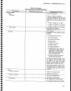
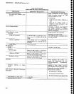
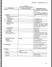
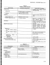
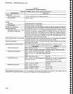
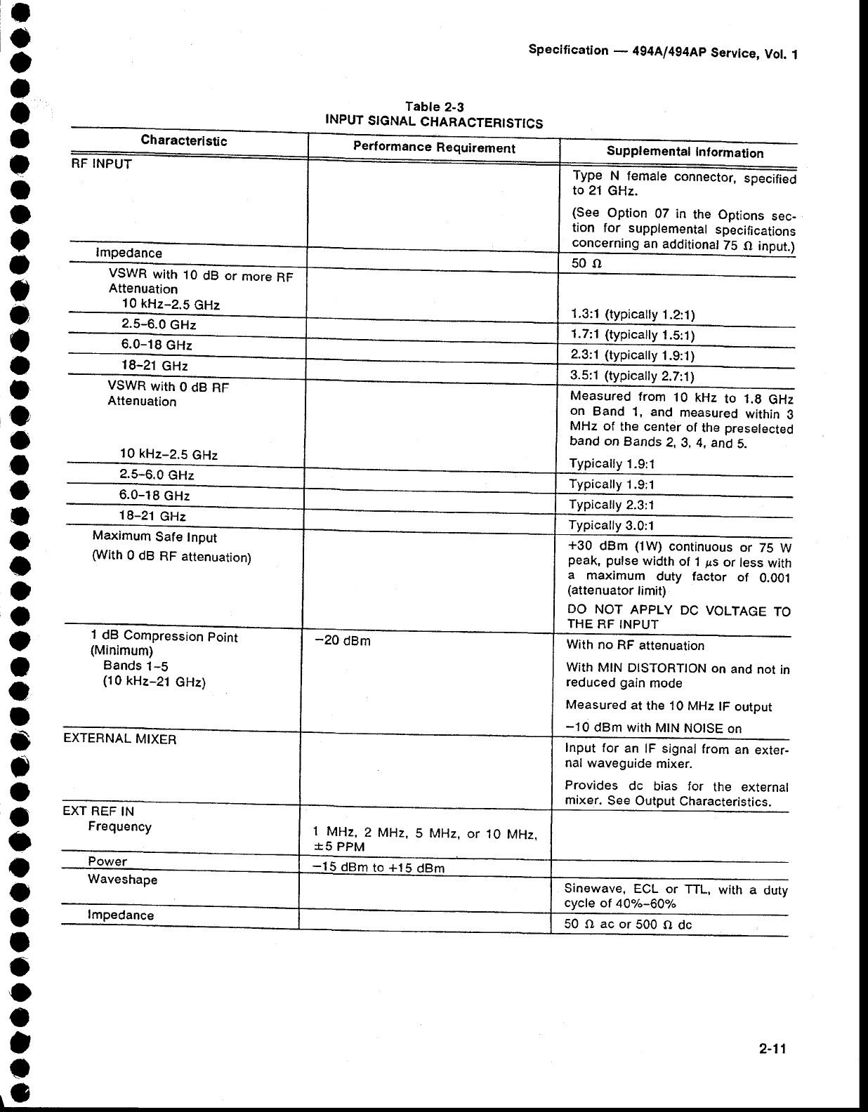
Tabte
2-3
INPUT
SIGNAL
CHARACTERISTICS
Specification
-
4g4Al494Ap
Service,
Vol.
1
Supplemental
Inf
ormaton
Type
N
female
connector,
specifieO
to 21
GHz.
(See
Option
07 in
the Options
sec-
tion
for
supplemental
specifications
concerning
an
additional
75
O input.)
50()
1.3:1 (typically
1.2:1)
1.7:1 (typically
1.5:1)
2.3:1 (typically
1.9:'t
)
3.5:1
(typically
2.7:1)
Measured
from
'1
0 kHz
to 1.9
GHz
on
Band
1, and
measured
within
3
MHz
of
the
center
of
the
preselected
band on
Bands
2,3,4,
and
5.
Typically
1.9:1
Typically
1.9;'l
Typically
2.3:1
Typically
3.0:1
+30
dBm
(1W)
continuous
or
75
W
peak,
pulse
width
of
1
ps
or
less
with
a
maximum
duty factor
of
0.001
(attenuator
limit)
DO
NOT APPLY
DC
VOLTAGE
TO
THE
RF INPUT
With
no
RF
attenuation
With
MIN
DISTORTION
on
and
not
in
reduced gain
mode
Measured
at
the 10 MHz
lF output
-10
dBm with
MtN
NOTSE
on
Input
for
an
lF signal
from
an
exter-
nal waveguide
mixer.
Provides
dc
bias
for
the external
mixer.
See
Output
Characteristics.
Sinewave,
ECL or
TTL,
cycle
of
40%-60%
with
a
duty
1
MHz,
2 MHz,
S MHz, or
10
MHz.
*5
PPM
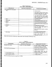
-15
dBm
to +15
dBm
lmpedance
50Oacor500Odc
2-11