


o
o
o
o
o
o
a
o
o
a
o
a
o
o
o
I
a
o
o
o
o
I
o
o
o
o
o
O
I
I
o
o
O
o
I
I
o
O
O
o
a
o
o
o
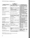
4.
Check
Center
Frequency
Accuracy
.
This
is
a
two
part
procedure;
part
I
checks
center
frequency
accuracy
with
the
1st
LO
unlocked,
part
ll
checks
accuracy
with
the l
st
LO
phase
lockecl.
A front
panel
CAL
should
be
done
before
performing
this
check.
Part
|
-
lst
LO
not
phase
Locked
Accuracy
with
the
.l
st
LO
unlocked
is
:r
{(20% of
the
Span/Div
or
Resolution
Bandwidth,
whichever
is
g.relter)
+
(CF x
Reference
Frequency
Eror)
+
15N
kHz).
The
1st
LO
is
not phase_locked
in
Fre_
quency
Span/Div
settings
>200
kHz.
For
Span/Div
settings
(200t<Hz,
the 1st
LO
may
be
unlocked
by
first
going
to
an
unlocked
Span/Div
setting
anO
Oisa6ling
tre-
quency
corrections
(Btue-SHtFT
t
0
dB),
then
spanning
down
to
a
Span/Div
setting
(200
kHz.
Quantity
N
is
the 1st
LO
harmonic
number
used
for
the
first
conversion.
press
HELp
and
BAND
(down)
for
the
value
of
N.
The
frequency
counter
must
be clocked
by
an
external
reference
standard.
a.
Use
a
Frequency
Counter
with
a
prescaler
to
measure
the
fundamental
output
frequency
of
the
Comb
Generator
(Comb
Generator
source
output
excluding
the
Comb
Generator
Module).
b.
Make
a
note
of,the
measured
frequency,
which
is
approximately
500
MHz.
This
is
the fundamental
fre-
quency
referred
to in
Tabte
4-2,
and
will
be
used
to
determine
each
center
frequency
checked.
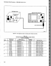
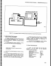
c.
Connect
the
test
equipment
as
shown
in
Figure
4-3.
d.
Set
the
Spectrum
Analyzer
controls
as
follows:
REF
LEVEL
-10
dB
SPAN/DIV
210
k:Hz
AUTO
RESOLN
On
VERT|CAL
DTSPLAY
10
dB/DtV
MIN
RF
ATTEN
dB
O
PEAK/AVERAGE
Fuily
Ctockwise
TIME/DIV
AUTO
e.
use
the
Data
Entry
keypad
to set
the
CENTER
FREQUENCY
to the
fundarnental
trequency
noted
,n
part
b
{rounded
off
to
the nearest
kHz).
Performance
Check
procedure
-
4g4ful4g4Ap
Servlce
Vol.
.l
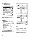
f.
Check
that
the
disptayed
signat
is
within
0.271
divisions (5T
kHz)
of center
screen.
-
S.
Continue
checking
frequencies
as
indicated
in
Table
4-2
as
per
the foilowing
example:
Check
Center
Frequency
Accuracy
at 19.5
GHz
Fundamental
indicated
by
frequency
counter
:
499.99831
MHz.
Deternine
Center
Frequency
to
the nearest
kHz:
Fundamental x
37 (from
Table
4-2)
0.499998
GHz
x
37
-
18.a99926
GHz
Use
Data
Entry
keypad
to s€t
CENTER
FRE_
QUENCY
to 18.499926
eHz.
Check
that
the
disptayed
signat
is
within
0.424
divi_
sions (89
kHz)
of
center
screen.
lf a
particular
check
should
fail,
measure
the fundamental
frequency
and
recheck.
Part
ll
-
lst LO
Phase
Locked
Accuracy
with
1st LO
tocked (SPAN/DIV<200
kHz
for
band 1
and
bands
5
through
12,
and
SPAN/D|V<10O
kHz
for
bands 2
through
4) is
+(20%
of
the
Span/Div
or
Resotution
BandwiOth,
whichever
is greater)
+
(CF
x
Reference
Frequency
Eror) +
(2N
+ 25)Hz
.
a.
Appty
the
cAL
ouT
signat
to
the
RF tNpuT.
b.
Set
the
Spectrum
Analyzer
controls
as
follows:
CENTER FREQUENCY
100
MHz
REF
LEVEL
-20
dBm
MIN
RF ATTEN
dB
O
SPAN/DIV
50
Hz
T|ME/D|V
AUTO
VERT|CAL
DTSPLAY
2 dB/DtV
AUTO
RESOLN
On
TRIGGERING
FREE
RUN
c.
Reset
the REFERENCE
LEVEL
to bring
the
top
of
the signal
below
the dot
marker.
d.
Check
'l
00 MHz
center
frequency
accuracy
by
measuring
the deviation
of
the
100 MHz signal
from
the
dot
marker.
Error must
not
exceed *.(20T"
of
the
Span/Oiv)
+
(25
+
2N) or
r,g7
Hz
(*9.7
minor
division).
The
factor
(CF
x
10-7) is
canceled
when
the
CAL OUT
signal
is
used.
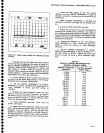
e.
Repeat
this
procedure
to check
the center
fre-
quency
accuracy
to 1.8
GHz in
100 MHz
increments.
Reset
the BEF
LEVEL
as
nec€ssary
to
observe
the
comb
of
100 MHz
markers
at
the
upper
end of
the
range.
4-7