o
o
a
o
o
o
a
o
o
I
I
t
o
a
a
o
a
o
o
o
a
I
o
O
o
o
t
o
I
O
t
a
o
a
a
O
O
I
O
o
o
o
o
o
Performanee
Check
procedure
_
4g4Al4g4Ap
Servlce
Vol.
1
SPECTRIfr
AI{I.AYZER
UI{OER
TEST
coME
OENERATOR
MOOULE
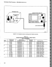
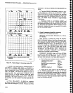
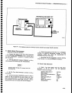
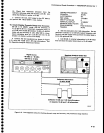
Figure
4-7'
Test
equipment
setup
for
checklng
frequency
span/Dlv
and
sweep
Time/Div
accuracy.
9.
^C.*:*_qyegp
Time
Accuracy
(Within
S%
of
the
rate
serecitJi'
a.
Connect
the
output
of
the
Time
Mark
Generator
to
the
rear-panet
MARKERI/|DEO
input.--6'onnect
pin
1
of
J104
ACCESSORY
connector
ti-groiio
(connect
pin
1
to
pin
S).
- .b. _Set
the
Spectrum
Analyzer
TIME/D|V
to
20 ps,
and
activate
zERo
SpAN
ano
tNT
rireb-lnjr.rc.
Disable
digital
storage
for
sweep
times
fas-
t€r
than
2
ms.
c.
Set
the Time
Mark
Generator
controls
for
20
ps
time
marks.
d.
use
the
horizontal
poslTloN
controt
to
align
a
marker..on
rhe
1st graticute
tine
(see
Fd;;
4-B),
then
check
the
displacement
of
markers
trori-ineir
respec-
tive positions
over
the
c€nter
eight
divisions.
Marker
dispfacement
must
not
exceed
S/o
over
the
display.
e.
check
the
accuracy
of
the
20
ps
to
5 s
TIME/D|V
::l!'!.S_r
by
apptying
appropriate
markers
,or
each
TIME/DlV
setting
and
noting
the
displac€ment
as
described
in
part
d
of
this
step.
f.
Disconnect
the-test_equipment,
and
the
shorting
strap
from
pin
1 of
Jl04
ACCESSORy
connector.
10.
Check
Pulse
Stretcher
a.
Apply
.1 ms
time
marks,
Generator,
to
the
RF
lNpUT.
Analyzer
controls
as
follows:
CENTER
FBEOUENCY
ZERO
SPAN
RESOLUTTON
BANDWIDTH
REF
LEVEL
VERTICAL
DISPLAY
TtME/DtV
VIEW
A and
VIEW
B
TRIGGERING
from
Set
the
Time
Mark
the
spectrum
2.0 MHz
On
100
kHz
0
dBm
10
dB/Dtv
.1 ms
off
INT
4-13


