


Malntenance
-
tl94A/494Ap
SeMce
Vot.
1
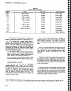
Schematic
diagrams
list
the
Tektronix
part
No.
(670-xxxx-)
for
the assembty
or
board atong
with
the
assembly
number
(e.9.
AS0)
and
name.
The
tast
two
digits or
sufftx of
the
part
number
are
not indicated
on
the
diagram, however,
they are
list€d in
the
El€ctrical
Parts section.
These
two
digits
rsflect
changes
or
modifications
to
the
assembly
or
board.
When a
change
is made
to the assembly
the
suffx
rolls one
digit. The
diagram
indicates
these changes
with
a
grey
tint
drawing of
the
original
circuit
or if
a
component
changes
value
the symbol is
enclosed
with a
grey
tint
box.
When
a
major
modification
is
made
to
an
assem-
bly
or
board
and
it
is
no
longer
compatible
with
eadier
instruments
a
nsw
part
number
ls asslgned
and a
separate
schematic
with associated
illustrations
are
added.
all
diagrams
indicate
the new
part
number
and
the
instrument
serlal
number
break.
lf the
assembly
is
compatible
with
earlier
lnstruments
and
the change
is
significant
enough
to require
a
separate
schematic,
this
will
also
be
identified.
Corrections
to
the
manual
and
instrument
modifications
are
documented
by ad<ling
conection
pages
behind a
tabbed
page,
labeled
Change
Information,
at
the rear
of
the manual.
Check
this Change Information
section for
changes
to the
manual
or
thE
instrument.
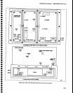
Circult
Board
lllustadons
and
Component
Loeator
Gharts
-
Electrical
components,
connectors,
and test
points
are id€ntifisd
on circuit
board illustrations
that
are
located
on
the insidg
fold of
the corresponding
cir-
cuit
diagram
or
the
back of
the
preceding
diagram. A
grid
on
the
circuit
board illustration
and
the
circuit
sch€rnatic,
plus
a look-up
tabl€.
provide
the means
to
quickly
locate
components
on either
the diagram or
the
circuit
board.
ln
most
cases,
circuit
numbers
are
assigned
accord-
ing
to the
physical
location
of
the component
on
the
board
or
assembly.
The
first
digit
designates
the row
of
a
grid,
the
second
the
column,
with
the last
two
reserved
as an expander.
Three
digit numbers
desig-
nate chassis mounted
compon€nts.
Diagnostcs
-
The
spectrum
analyzer
contains
firmware
that
will
assist
in locating
trouble in
the
fre-
quency
control
system
and
the
power
supply.
This
diagnostic
information
is
part
of
this section.
General
Troubleshooting
Techniques
Before using
test
equipment,
to
measure
across
static-sensitive
components
or
assemblies,
be certain
that
voltag€s
or current
supplied
by the
test equipment
does not
exceed
th€ limits of
the components
to be
tested.
6-4
Try
to
isolat€
the
problem
to
a component
through
signal analysis. Determine
that
circuit voltages
will not
damage
the replacement.
Semlconductor
Checks
-
Semiconductor
failures
account tor
the
majority of electronic
equipment
failures. All semiconductors
are
soldered
to
the
boards
to
reduce
pin
contact
problems.
The following
guide-
lines
should
be
observed
if
you
substitute any
of
these
components.
1.
Tum
the
power
off
before removing
an assembly
or
board.
2.
Use a
de-soldering tool
and 25 W
or less solder-
ing iron
to
remove the components.
3. Use
only
good
components for
substitution.
Be
sure
the new
component
is inserted
into the
board
properly
before
soldering. Refer
to
the
manufacturer's
data
sheet for
integrated
circuit
and
transistor lead configuration.
lf a substitute is not available,
check
the
transistor
or
MOS FET with a
dynamic tes-
ter such
as
the TEKTRONIX Type 576
Curve Tracer. Static
type testers,
such as
an ohmmeter. can
be
used to check the
resistance ratio across
some
semiconduc-
tor
junctions
if
no other method is available,
however, DO NOT MEASURE RESISTANCE
ACROSS
A
MOS FET to
avoid
damage
from static
charges.
Use the
high
resis-
tance
ranges
(R
x
1k or higher) so the
external
test
current is limited
to
less than
6
mA. lf uncertain, measure the
external
test
current with
an
ammeter.
Resistance
ratios across base-to-emitter
or
base-to-
collector
junctions
usually
run 100:1
or
higher. The
ratio is
measured by
connect-
ing
the
meter leads
across
the terminals.
note
the
reading,
then
reverse
the
leads
and note
the
second reading.
Dlode
Checks
-
Most
diodes
can
be
checked in
the
circuit
by taking
measurements
across the
diode
and
comparing these
with voltages listed
on
the
diagram.
Forward-to-back resistance
ratios
can
usually
be taken by
referring to the
schematic
and
pulling
appropriate
transistors
and
pin
connectors
to
remove
low resistance loops around
the
diode.
Do not
use
an
ohmmeter
scale with
a high
external
current to
check diode
junctions.
Do not check the forward-to-back
resis-
tance
ratios of mixer
diodes.