


G.
Sweep (refer
to
diagram
3l)
The
microcomputer
writes
to registers
0F
and
1F
to
control
sweep
rate,
mode.
holdott,
interrupts,
and
triggEring.
H.
Span
Attenuator
(refer
to
diagram
32)
Registers
75
and
76
control
the
span
attenuator.
l.
lst
LO
Driver
(refer
to
diagram
33)
Register
72
controls
functions
on
the
1st
LO
Driver
board.
Register
ZE
is
added
to make
the
pEAKing
con-
trol
programmable.
J.
Preselector
Driver
(refer
to
diagram
34)
Register
77
controls
functions
on
the
preselector
Driver.
The
single
bit DB3
responds
on
the data
bus
to
indicats
that
the
board
is
instaileO
when
the
microcom_
puter
performs
a
read
at
F7.
K
CENTER/MKR
FREQUENCy
Controt
(reter
ro
diagram
35)
.R€gisjer
70
is
provid€d
for
control
functions
and
register
71
is
provided
for
data
values
for
center
fre_
quency
DAC(s).
A
read,
F0,
returns
the
results
of
a
comparison
of
the
DAC
output
voltage
and
a
memory
voltage.
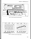
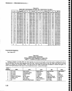
L.
Auxiliary
Synthesizer
Control (refer
to
diagram
371
Register
7D
accepts
data
to set
the
synthesizer
chip,
U4041,
to output
200
MHz
to
220
MHz
in
400
kHz
steps.
Values
of
R,
A,
and
N
are
given
to
determine
the
output
frequency
as
given
by
the
formula
fout
:
(l/RXNP+A)
where
R,
the reference
division
ratio,
is
set
at
5 and
p
is
the
prescale
value
of
32.
N
values
needed
are
3.1
through
34, while
A
ranges
from
0 to
31.
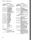
(fable
6_14
shows
the
fou, results
for
given
N
and
A values.)
M. Phase
Lock (refer
to
diagram
39)
,Register
73
accepts
data
to
preload
the
+2n
counter
and
control
the
synthesizer.
Successive
reads
from
register
F3 obtain
status
and
counter
outputs.
After
the
counter
output
register
selector
is
reset,
three read
cycles
return
status
bits
and
counter
bits in
lhg
To"l
significant
byte
and
the remaining
counter
bits
in
following
bytes.
Maintenance
-
4g4Al4g4Ap
Servlce
Vol.
l
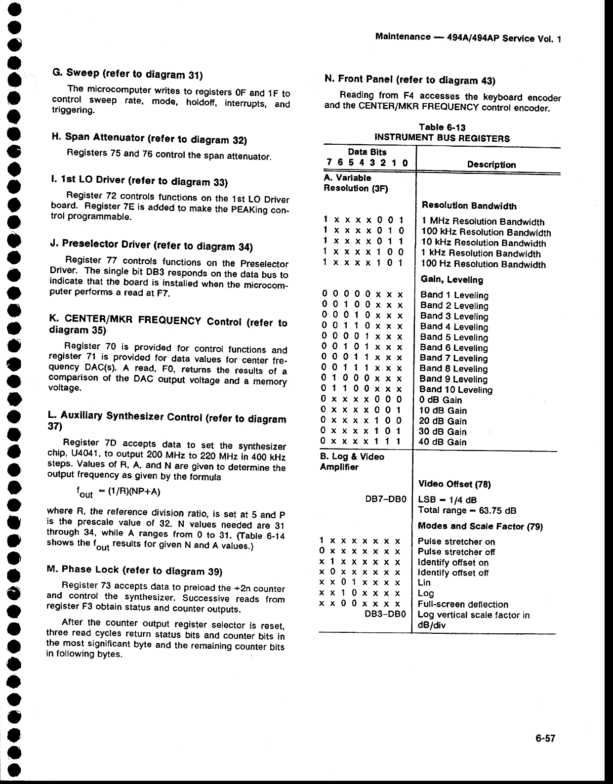
N. Front
Panel
(refer
to diagram
43)
Reading
from
F4 accesses
the
keyboard
encoder
and
the
CENTER/MKR
FREQUENCy
controt
encoder.
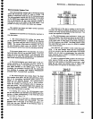
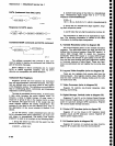
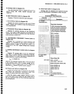
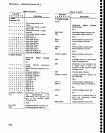
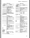
Tabte
6-13
INSTRUMENT
BUS
REGISTERS
1xxxx001
1xxxx010
1xxxx011
1xxxx100
1xxxx101
Data
Bits
76543210
A. Variable
Resolution
{3F}
B.
Log
& Video
Ampllfier
Description
Resolution
Bandwidth
I
MHz
Resolution
Bandwidth
100
kHz
Resotution
Bandwidth
10 kHz
Resolution
Bandwidth
1 kHz
Resolution
Bandwidth
100
Hz
Resolution
Bandwidth
Galn,
Levellng
Band
1
Leveling
Band
2 Leveling
Band
3 Leveling
Band
4 Leveling
Band
5
Leveling
Band
6 Leveling
Band
7
Leveling
Band
I
Leveling
Band
9
Leveling
Band
10
Leveling
0 dB
Gain
t0
dB
Gain
20
dB
Gain
30
dB
Gain
40
dB
Gain
Video
Olfset
{78}
LSB
-
114
dB
Total
range
-
63.75
dB
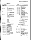
Modes
and
Scale
Factor
O9)
Pulse
stretcher
on
Pulse
stretcher
off
ldentify
offset on
ldentify
offset
off
Lin
Log
Full-screen
deflection
Log
vertical
scale
factor in
dB/div
00000xxx
00100xxx
00010xxx
00110xxx
00001xxx
00101xxx
00011xxx
00111xxx
01000xxx
01100xxx
0xxxx000
0xxxx001
0xxxx100
0xxxx101
0xxxx111
DB7-DBO
lxxxxxxx
0xxxxxxx
xlxxxxxx
x0xxxxxx
xx0lxxxx
xxl0xxxx
xx00xxxx
DB3-DBO
6-57