


Performance
Check
procedure
-
4g4Al4g4Ap
Service Vol.
1
34.
Check
Option
42110
MHz
OUT
Level
((0
dBm
for
Band
1)
(>.-40
dBm for
Band
5)
.
a.
Tune
the
Spectrum
Analyzer
CENTER
FRE_
QUENCY
to 100
MHz.
b.
Connect
a
signal generator
to
the
RF
lNpUT.
Set the
signal
generator
output
frequency
to i00
MHz,
and
output
level
to
-30
dBm.
c.
Set
th€ REF
LEVEL
to
-gO
dBm.
and RF
ATTENUATION
to
O dB.
d.
Switch
the
FREQUENCY
SPAN/D|V
control
towards
zero span
while
keeping
the signal
centered
with
the
CENTER
FREQUENCY
controt.
The
crt
SPANiDIV
readout
will
indicate
10
ms
when
zero
span
is reached.
e. Monitor
the 110
MHz
OUT with
a
test
spectrum
analyzer.
f.
set
the CENTER
FREOUENCY
controt
to
peak
the signal
displayed
on
the
test spectrum
analyzer.
g.
check
that
the
110
MHz
tF
ouT
output
tevet is
(0
dBm
typically
-8
dBm
for
Band 1.
-
h.
Connect a
signal generator,
capable
of
delivering
18
GHz,
to the RF lNpUT.
Set
the
signal generator
out-
put
frequ€ncy
to 18
GHz
and
output
level
to
-30
dBm.
i.
Reset
the
Spectrum
Anatyzer
CENTER
FRE-
OUENCY
to
18
GHz
on
Band
5,
REFERENCE
LEVEL
to
-30
dBm,
and RF
ATTENUATTON
to
0 ctB.
j.
Switch
thE FREOUENCY
SPAN/D|V
control
towards
zero
span
while keeping
the
signal
centered
with
the
CENTER FREQUENCY
control.
The
crr
SPANIDIV readout
will indicate
10 ms
when
zero span
is reached.
k. set
the CENTER
FREQUENCY
controt
to
peak
the
signal
displayed
on the
t€st
spectrum
analyzer.
l. check
that the
110
MHz tF
ouT levet
is
)-40
dBm.
35. Check
Optiopn 4211O MHz
lF
Output
Bandwidth,
Center
Frequency,
Bandpass
Ripple, and
Symmetry About 110 MHz
(Bandwidth:
>5
MHz)
(Center
Frequency:
108.5 MHz-l11
.5
MHz)
(Bandpass
Ripple;
<0.5
dB)
(Symmetry:
*1.0
MHz)
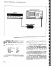
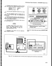
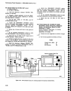
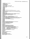
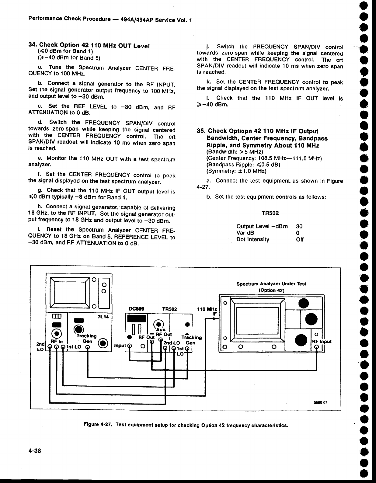
a. Connect
the
test
equipment
as shown in
Figure
4-27.
b.
Set the
test
equipment
controls as follows:
TR5O2
Output
Level
-dBm
30
Var
dB 0
Dot Intensity
Off
o
o
o
o
I
o
e
o
o
o
o
I
I
o
o
o
o
I
I
o
o
o
o
o
t
o
I
o
o
I
I
O
I
o
o
I
I
o
o
o
o
o
o
o
H:H
ooo
ull
I
e
RF
In
I
O
Trrckiog
Gcn
7L14
o
Spectrsm
Analyzer
Under Test
(Option
42)
11O
MHz
IF
.I
ll
RF
o
Q.
Q 15o'it
r'i"line
Input
2ndLO Gcn
4-38
Figure
4-27. Test
equlpment
setup
lor
checking option 42 frequency
characterlstics.