


o
o
o
o
o
o
o
o
o
o
o
o
o
o
o
o
o
o
o
o
o
o
o
o
o
o
o
o
o
o
o
o
o
o
o
o
o
o
o
o
o
o
o
o
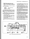
2.
^qlult
Z-Axis
and
High
Votrage
Circuits
{110?1,
R1027,
Rlogo,-R1ost,
tno-ili0s8
on
the
Z-Axis
board;
R2O4A
and
R3030
on
the
High
Vottage
board)
a.
Switch
POWER
off
and preset
the
foilowing
Spectrum
Anatyzer
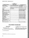
controls:
Adjustment
Procedure
-
494A/494Ap
Service
Vot.
1
(4)
Set
the INTENSITY
control
such
that
the voltage
at
the coltector
of
e4059
is
5.5 V
higher
than
the
voltage
noted
in
part
d,
subpart
1.
(5)
Use
the
non-metallic
screwdriver
to adjust
Crt
Bias,
R2040,
counterclockwise
until
the crt
beam
is
visible,
then
clockwise
until
the
beam
dot
just
extin-
guishes,
with
the
scr€en
shaded.
(f
no
dot
1?pea.tj:
with
the adjustment
fuily
counterctockwise,
this will
be
the bias
setting.)
(6)
Turn
the tNTENStTy
ctockwise
until
a
dot
is
visi_
ble
then
defocus
th€ dot
with
thE Focus
adjustment,
R3033.
Adjust
Astigmatism
R1OS8
(Figure
l5*lZl
tor
a
round
dot
then
refocus
with
R3033
for
ttre
smailest
and
sharpest
dot.
fl)
Turn
the
tNTENStTy
counterclockwise
untit
the
dot
just
disappears,
and
again
measure
the
collector
voltage
at
Q4058
or
e4059.
Vottage
shoutd
equat
or
exceed
that
set
in
part
d, subpart
4.
ll
the voltage
is
less,
repeat
the
procedure
for
setting
Crt
bias.
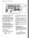
e.
Adjust
the
Crt cathode
curent
as
follows:
(1)
Switch
POWER
off,
then
remove
p4096
(Figure
5-3) on
the
High
Vottage
board.
Turn
|NTENSIW
fully
clockwise,
MANUAL
SCAN fuily
counterclock_
wise,
and
ensure
that the
TIME/DIV
is
in
the
MNL
position.
S€t
the
Intensity
Limit
R1022,
on
the
Z_
Axis
board,
(Figure
5-2) fuily
clockwise.
(2)
Connect
the voltmeter
between
Tp402g
(Figure
5-3)
and
the
ground
lug
on
the crt
shietd.
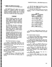
INTENSITY
TIME/DIV
MANUAL
SCAN
Fully
Counterclockwise
MNL
Midrange
b. Remove
the cover
over
the
Z-Axis
and
Sweep
boards.
Set
the
Intensity
Limit
R1027.
on
fi,"
Z_Axis
Plr.l(Figure
5-2)
fuily
counterctockwise
anO
Crt
Bias
12010,.
on
rhe
High
Vo[age
board
figure
5_3)
fuily
clockwise.
c.
Switch
POWER
on-and,
after
the
power-up
state
has
stabilized,
chang_e
the
Vertical
OiJpf"V
mode
to
2
dBlDtv.
DeactivatehEADOUT,
viEw
l,'""0
vtEW
B.
d.
Adjust
Crt
Bias
as
follows:
(1)
Using
a
voltmeter
in
the
20
V
range,
measure
and
record
the collector
voltage
of
a+06e
or
e4059
on
the
Z-Axis
board (See
Figuie
5-1b.)
(2)
Turn
the
INTENSITy
clockwise
until
a
crt
beam
dot appears
on
screen.
(3)
Focus
the
dot
by adjusting
Rgogg
on
the
High
v€ttage
board
(Figure
s_3)
toi
tne
smailest
round
dot.
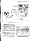
5-5
ASTmAnSt
Rr058
GEOTETRY
A D{TEilSTY
Rrqm
Rr051
SWEEP
ACCURACY
R1002
POUER
STATUS
YERTICAL
GAIN
RlOGO
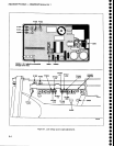
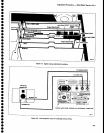
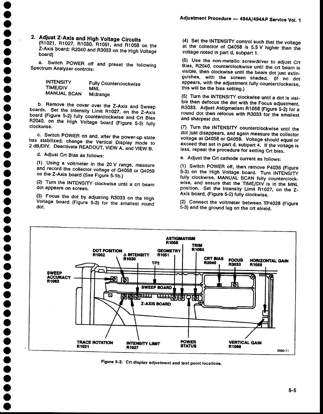
Figure
5-2.
Crt
display
adjustment
and test
point
locaiions.