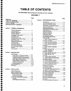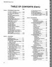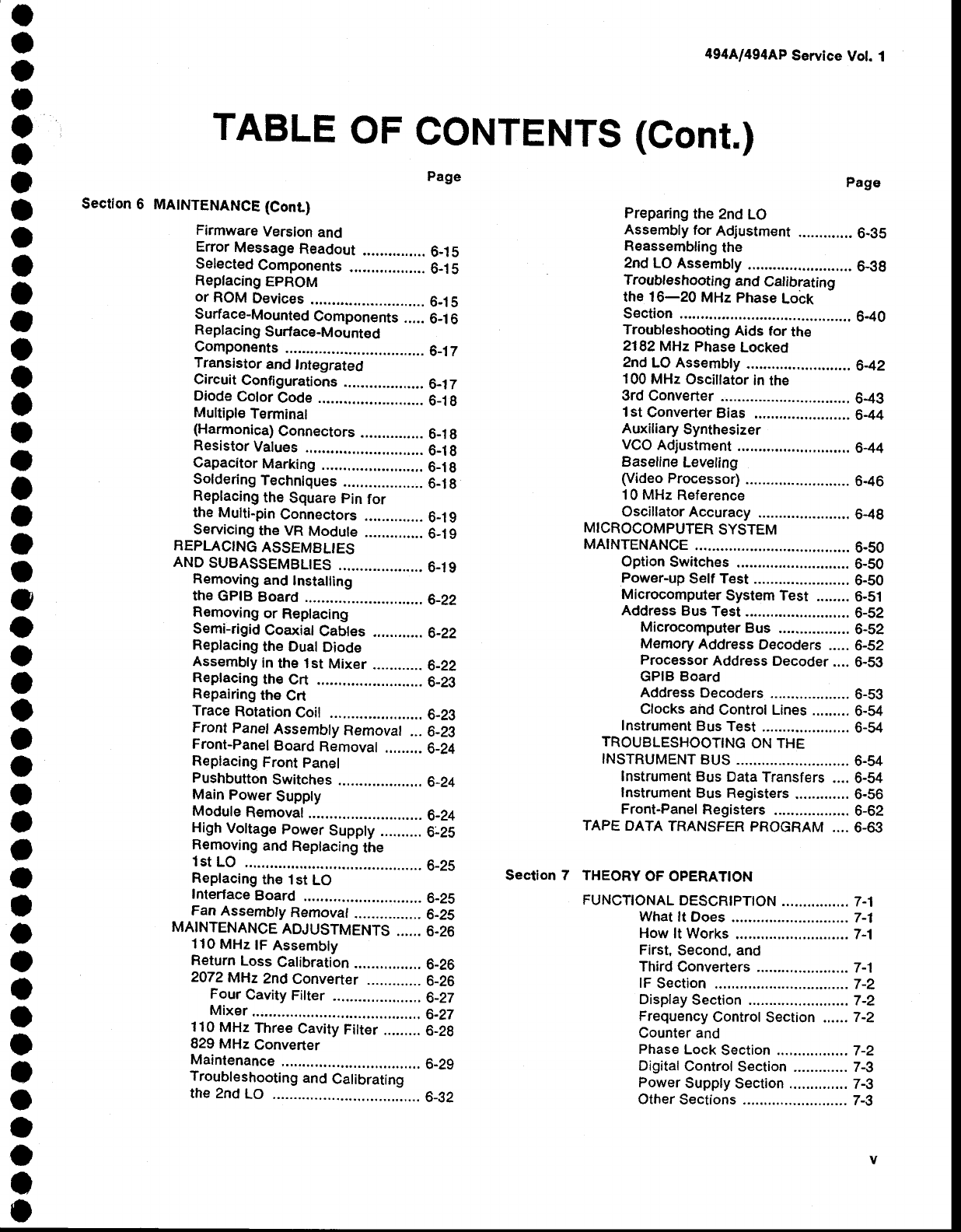
TABLE
OF
CONTENTS
(Conr.)
o
o
o
I
O
I
I
o
o
O
I
a
o
o
a
I
o
I
o
o
t
o
o
o
a
o
o
o
I
o
a
a
t
o
O
o
I
o
o
o
a
o
o
o
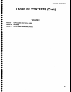
494A/494AP
Service
Vot.
1
Section
6
page
MAINTENANCE
(Conr)
Firmware
Version
and
Enor
Message
Readout
...............
6-1
5
Selected
Components
..................
6-1
5
Replacing
EPROM
or
ROM
Devices
........
6-15
Surface-Mounted
Components
.....
6_1
6
Replacing
Surface-Mount€d
Components
..............
6_17
Transistor
and
Integrated
Circuit
Configurations
................,..
6_1
7
Diode
Cotor
Code .........................
6_1
g
Multiple
Terminal
(Harmonica)
Connectors
...............
6_1
g
Resistor
Values
.........
6-1g
Capacitor
Marking
.....
6_1g
Soldering
Techniques
...................
6-1
g
Replacing
the
Square
pin
for
the
Multi-pin
Connectors
..............
6_1g
Servicing
the VR
Module
..............
6-1g
REPLACING
ASSEMELIES
AND
SUBASSEMBLTES
....................
6_19
Removing
and
Installing
the
GPIB
Board
.........6-22
Removing
or
Replacing
Semi-rigid
Coaxial
Cables
............
6_22
Replacing
the Dual
Diode
Assembty
in
the 1st
Mixer
............
6_22
Replaeing
the
Crt
......
6_23
Repairing
the
Crt
Trace
Rotation
Coil
...
6-29
Front
Panel
Assembly
Removal
...6-29
Front-Panel
Board
Removal
.........
6_24
Replacing
Front
panel
Pushbutton
Switches
....................
6_24
Main
Power
Suppty
Module
Removal
........
6_24
High
Vottage
power
Supply
..........
6_25
Removing
and
Replacing
the
lst
LO
..6_25
Replacing
the
l st
LO
Interface
Board
.........
6_25
Fan
Assembty
Rernovaf
................
6-25
MAINTENANCE
ADJUSTMENTS
......
6.26
110
MHz
tF
Assembty
Return
Loss
Calibration
................
6-26
2072MHz
2nd
Converter
.............
6_26
Four
Cavity
Filter
..........
...........
6_27
Mixer.........
...........,9-27
110
MHz
Three
Cavity
Fitter
.........
6_29
829 MHz
Converter
Maintenance
..............
6_29
Troubleshooting
and
Calibrating
the 2nd
LO
.............
..6-32
Page
Preparing
the
2nd
LO
Assembly
for
Adjustment
.............
6-35
Reassembling
the
2nd LO
Assembty
.....
6-9g
Troubleshooting
and
Calibrating
the 16-20
MHz Phase
Lock
Section
.....................
6-40
Troubleshooting
Aids
for
the
2182MHz
Phase
Locked
2nd
LO Assembty
.....6-42
100
MHz
Osciltator
in the
3rd Converter
...............................
649
l st
Converter
Bias
.....................,.
6-44
Auxiliary
Synthesizer
VCO
Adjustment
...........................
6-44
Baseline
Leveling
(Video
Processor)
.....
6-46
10 MHz
Reference
Oscillator
Accuracy
.. 6-49
MICROCOMPUTER
SYSTEM
MATNTENANCE
.............
....
6-50
Option
Switches
.......
6-50
Power-up
Self Test
...
6-50
Microcomputer
System Test
........
6-51
Address
Bus
Test
.....
6-52
Microcomputer
Bus
.................
6-52
Mernory
Address
Decoders
.....
6-52
Processor
Address
Decoder
....
6-59
GPIB Board
Address
Decoders
Clocks ahd
Control Lines
.........
Instrument
Bus
Test
TROUBLESHOOTING
ON THE
INSTRUMENT
BUS
Instrument Bus
Data
Transfers
....
Instrument
Bus Registers,............
Front-Panel
Registers
TAPE OATA
TRANSFER
PROGRAM
....
THEORY
OF OPERATION
FUNCTTONAL
DESCR|pTtON
............
.... 7
-1
What
lt Does
................-...........
7-1
How
lt Works
.......7-1
First,
Second, and
Third
Gonverters ...........
........... 7
-1
lF
Section
..-.........7-2
Display
Section
....7-2
Frequency
Control
Section
.,....
7-2
Counter and
Phase
Lock
Section .............,...
7-2
Digital
Control Section
............. 7-3
Power
Supply
Section ..............
7-3
Other
Sections
...............
.......... 7-3
6-s3
6-54
6-54
6-54
6-54
6-56
6-62
6-63
Section 7


