


Maintenance
-
4g4A/4g4Ap
Servlce
Vol.
I
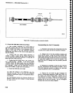
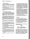
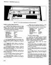
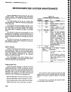
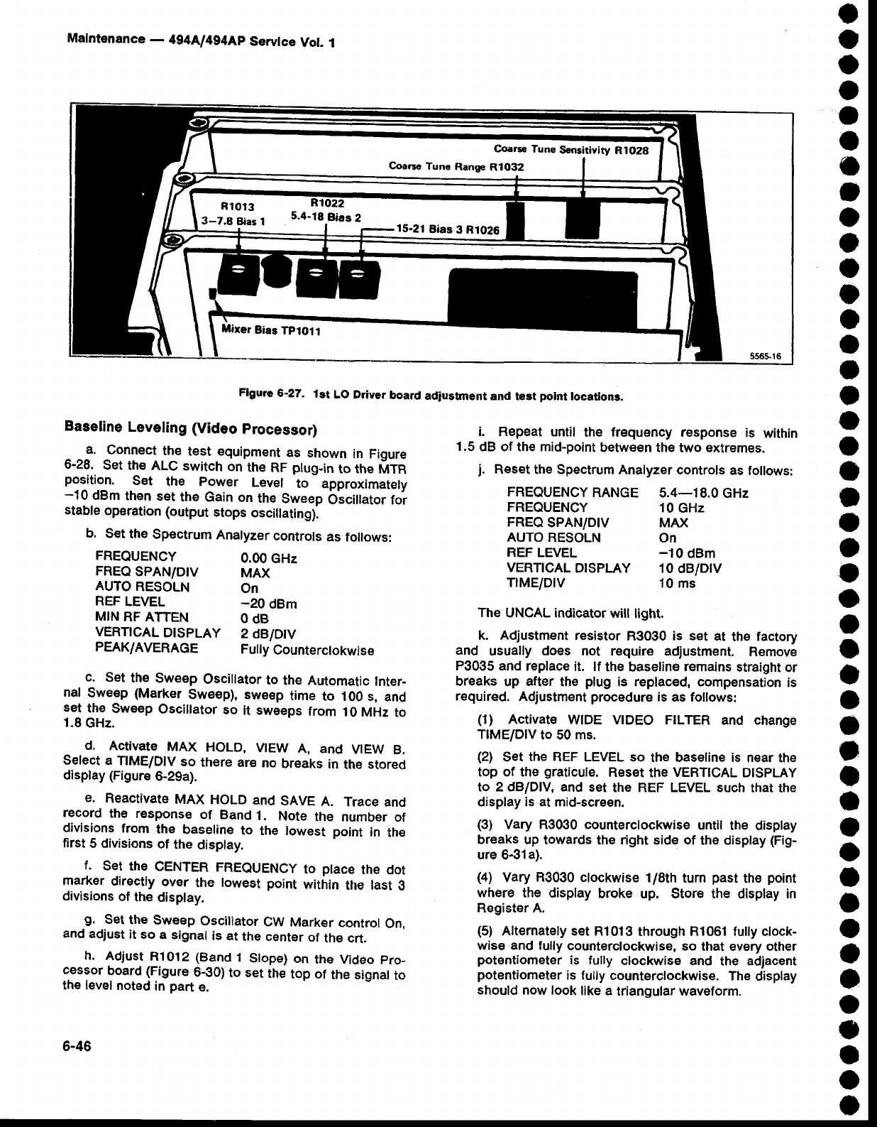
Flgure
5-27.
1st
LO
Ddyer
board
adjustment
and test
point
locatlons.
o
o
o
o
o
a
o
t
o
o
o
o
o
o
I
t
o
o
o
I
o
o
o
o
o
o
a
a
o
t
t
I
o
o
o
O
o
o
)
o
o
I
o
o
Baseline
Leveling
(Video
processor)
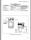
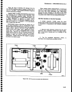
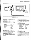
a.
Connect
the
test
equipment
as
shown
in
Figure
6-28.
Set
the
ALC switch
on
the
RF
ptug-in
to the
MTR
position.
Set
the
power
Levef
to approximately
-10
dBm
thsn
set
the
Gain
on
the
Sweep
bscittator
foi
stable
operation
(output
stops
oscillating).
b. S€t
the
Spectrum
Analyzer
controls
as
follows:
FREOUENCY
0.00
GHz
FREQ
SPAN/D|V
MAX
AUTO
RESOLN
on
REF
LEVEL
-20
dBm
MIN
RF
ATTEN
O
dB
VERT|CAL
DTSPLAY
2
dB/Dtv
PEAK/AVERAGE
Fuily
Counterctokwise
c.
Set
the
Sweep
Oscillator
to
the Automatic
Inter-
nal
Sweep
(Marker
Sweep), sweep
time
to 100 s,
and
se!
lhg
Sweep
Oscillator
so
it sweeps
from
10 MHz
to
1.8
GHz.
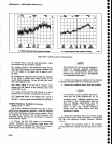
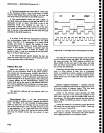
d.
Activate
MAX
HoLD,
VIEW
A,
and
VIEW
B.
Select a
TIME/DIV
so
there
ar€
no
breaks in
the stored
display
(Figure
6-29a).
e.
Reactivate
MAX
HoLD
and
SAVE
A.
Trace
and
record
the
response
of Band
1.
Note
the
number
of
divisions
from
the
baseline
to
the lowest
point
in
the
first
5 divisions
of
the
disptay.
f.
set
the
CENTER
FREQUENCY
to
ptace
the
dot
marker
directly
over
the
towest
point
within
the last
o
divisions
of
the
display.
-9.
Set
the
Sweep
Oscillator
CW
Marker
control
On,
ancl
adjust
it so
a signal
is at
the cent€r
of
the
crt.
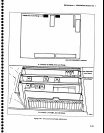
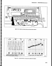
h.
Adjust
R1O12
(Band
1
Stope)
on
the Video
pro-
cessor
board (Figure
6€0)
to
set
the
top of
the
signalto
the level
noted
in
part
e.
6-46
i.
Repeat
until
the frequency response
is
within
1.5
dB of the mid-point
between
th€ h^/o extremes.
j.
Reset
the Spectrum
Analyeer controls
as follows:
FREQUENCY
RANGE
5.4-18.0
GHz
FREQUENCY
10
GHz
FREQ
SPAN/DIV
MAX
AUTO RESOLN
ON
REF LEVEL
-10
dBm
VERTTCAL
DTSPLAY
10 dB/DlV
TIME/DIV
10
ms
The
UNCAL indicator
will
light.
k. Adjustment
resistor
R3030 is
set
at
the
factory
and
usually
does
not require
adjustment.
Remove
P3035 and
replace
it. lf
the baseline
remains
straight
or
breaks
up
after
the
plug
is replaced. compensation
is
required.
Adjustment
procedure
is
as follows:
(1)
Activate
wlDE vtDEo FTLTER
and change
TIME/DIV
to 50
ms.
(2)
Set
the REF
LEVEL so
the
basetine
is
near
the
top of the
graticule.
Reset
the
VERTICAL
DtspLAy
to 2 clB/Dlv, and
set
the REF LEVEL such
that the
display
is at
mid-screen.
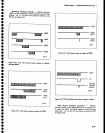
(3)
Vary R3030 counterclockwise
until the
display
breaks
up towards
the
right
side
of
the display
(Fig-
ure
6-31a).
(4)
Vary
R3030
clockwise
1/8th
tum
past
the
point
where
the display
broke
up.
Store the
display in
Register A.
(5)
Alternately set
Rl013
through
Rl061 fully
clock-
wise and fully
counterclockwise,
so
that every other
potentiometer
is fully
clockwise and
the adiacent
potentiometer
is fully
counterclockwise.
The
display
should
now look
like a
triangular waveform.
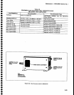
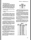
Coarse
Tune
Range
R1032
3_Z.B
Etias
I
5.4-18.Bias
2
15-21
Bias
3 R1026
Mirer
Bias
Tptoll