


I
o
o
t
o
t
o
I
o
o
I
I
o
a
a
a
a
O
a
a
o
o
o
o
a
o
o
a
a
I
a
o
I
o
o
o
o
I
O
o
I
o
I
o
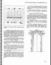
Perlormance
Check
procedure
_
4g4Ll4g4Ap
Servlce
Vot.
1
g.
Check
the
resolution
bandwidths
and
shape
fac_
tors
for
the
100
kHz
(300ftHa
for
Option
bA,
10
kHz,
1
kHz,
and
100
Hz
fitters.
Shape
factlistroufd
be
7.5:1
or
less.
h.
RESET
thE
RESOLUTION
BANDWIDTH
tO
'IO
HZ,
qlglptv
to
50 Hz,
and
VERlCnl.'drdpr-ry
ro
2
dB/Dlv.
i.
Check
the
resolution
bandwidth
and
shape
factor
of
the 10
Hz
fitter.
Shape
factor
should
i"
iZrt
or
tess.
12.
Check
Catibrator
Output
(-20
dBm
*0.3
dB)
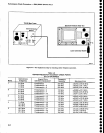
Apply
a
100
MHz
signal
to
the
power
meter
through
a
3
dB
attenuator
anO
a
SOO
"d;t".
Set
the
generator
output
level
for
a
reading
of
_20
dBm
on
the
power
meter.
b.
Disconnect
the power
meter
from
the signal
gen_
erator,
and
connect
the
reference
signat
established
in
part
a
to
the
RF
tNpUT,
through
thd
same
50O
cable
and
3
dB attenuator.
c.
Set
the
Spectrum
Analyzer
controls
as
follows:
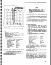
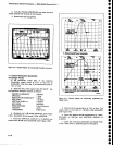
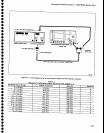
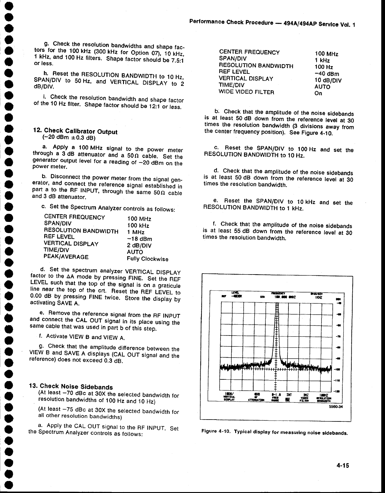
b.
Check
that
the amplitude
of
th€
noise
sidebands
is
at
least
50 dB
down
from
the
reference
lev€l
at
g0
times
the resolution
bandwidth
(3
divisions
away
from
the center
frequency
position).
See Figure
4-10.
c.
Reset
the
spAN/Dlv
to 1oo
Hz
and
set
the
RESOLUTTON
BANDWTDTH
to 10
Hz.
d.
check
that
the
amplitude
of
the noise
sidebands
is
at
least
50
dB down
from
the
reference
level
at
30
times
the resolution
bandwidth.
€.
Reset
the
spAN/Dtv
to 10 kHz
and
set
the
RESOLUTION
BANDWIDTH
to 1
kHz.
f.
Check
that
the amplitude
of
the noise
sidebands
is at
least
55 dB
down
from
the
reference
level
at
O0
times
the resolution
bandwidth.
CENTER
FREOUENCY
sPAN/DtV
RESOLUTION
BANDWTDTH
REF
LEVEL
VERTICAL
DISPLAY
TrME/DtV
WIDE
VIDEO
FTLTER
100
MHz
1
kHz
100
Hz
-40
dBm
10
dB/Dtv
AUTO
On
CENTER
FREQUENCY
SPAN/DIV
RESOLUTION
BANDWIDTH
REF
LEVEL
VERTICAL
DISPLAY
TfME/Dlv
PEAK/AVERAGE
100
MHz
100
kHz
1
MHz
-18
dBm
2
dBlDtv
AUTO
Fully
Clockwise
; .d. .Sel
the spectrum
analyzer
VERTICAL
DlSpLAy
factor
to th€
AA
mode
by
pressing
firuE.-'Set
the
REF
LEVEL
such
that
the
top'oi
the
siinat
is'on
a
graticute
line
near
the
top
of
the crt.
nesJt
ttre
neF
LEVEL
to
0.99
gP
by
pressing
F|NE
twice.
Store
ttre
display
by
activating
SAVE
A.
_e.
Remove
the
reference
signaf
frorn
the
nF
tNpUT
and
connect
the
CAL
OU.T
signll
in its place
using
the
same
cable
that
was
used
in
part
b
of
this
step.
f.
Activate
VIEW
B
and
VIEW
A.
g.
Check
that
the
amplitude
difference
between
the
VIEW
B
and
SAVE
A
disptays
(CAL
OUi
iignar
anO
the
reference)
does
not
exceed
b.S'Og.
13.
Check
Noise
Sidebands
(At
least
-70
dBc
at
30X
the
selected
bandwidth
for
,
resolution
bandwidths
of
100
Hz
and
10
Hz)
(At
least
-75
dBc
at
gOX
the
selected
bandwidth
for
all
other
resolulion
bandwidths)
1.
Appty
the
CAL
OUT
signat
to
the RF
tNpUT.
Set
the
Spectrum
Analyzer
controls
as
follows:
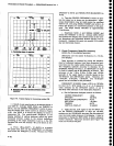
Figure
4-10.
Typical
disptay
for measuring
noas€
sidebands.
E
-St
cd
ra.C
rttr
-
|rq
n
{
{
-
_tt
-
-
-rl
-il4
-tt
t
ll{l
r
I
rrl
(
\
l4ftr
I
556034
4-15