


o
o
o
o
o
o
o
o
o
a
a
o
o
o
o
o
o
a
o
,
o
o
o
o
o
t
o
o
I
o
a
o
I
o
o
a
a
I
o
o
o
a
o
o
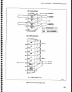
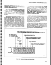
Accessories
lnterface (Diagram
44)
The Accessories
lnterface
board
(A90A76)
provides
access
to
the
instrument
bus, and
the
external
MARKER/VIDEO
input
and
controt
tine.
The
MARKERIVIDEO
input
is
through
a
coaxial
connector.
The
other
lines
are
availabls
through
the
ACCES_
SORIES connector.
Theory
of
Operatlon
-
4g4ful494Ap
Servlce,
Vol.
1
Iq
display
an Externat
signal
that
is
applied
to the
MARKEF/V|DEO
input,
putt
the
EXT
vtDEo
SEtect
tine
(pin
1 of
the
ACCESSORTES
connector)
tow.
The
instrument
bus
is
buffered and
brought
out
to
the
rear
panel
with
the lines
named
to
indacate
their
relation
to
the
internat
bus: ADV
for
DATA
VALID.
APOLL
for POLL.
etc.
Two
lines,
tNT
CONT and
DATA
BUS
ENABLE.
define
th€ instrument
bus/external
device
lnterface.
An
external
controller gains
control
by
pulling
the
INTER-
NAL
CONTROL
line tow.
This
disabtes
th€
internal
microcomputer's
instrument
bus
buffers
and
sets
th€
data
direction
of
buffers
U201S and
U2033.
In
this
state,
the
external
controller
sends
addresses
and
the
DATA
VALID
and
pOLL
signals
to
the instrurnent.
lt
also
allows
th€ instrument
circuits
to
s€nd
a
service
request
(SR)
signal
to
the external
controller.
For inter-
nal control,
the
buffers reverse
direction.
Data
buffer
U2038
transfers
data
to and
from
the
external
instrument
bus. Data
direction
depends
on
whether
control
is
internal
or external
and
on
what
the
address
is.
The
buffer
senses
the
most
significant
address
bit, AB7,
so
that when
in external
control.
the
upper
addresses
(AB7
high)
send
data to
the instrument
and
th€ lower
half of
the
addresses (AB7
low)
receive
data
from
the instrument.
For internal
control,
thE
data
direction
reverses.
The
DATA
BUS ENABLE
line
is
asserted
low
by an
external
device
to
€nable
the data
buffer.
As long as
this line
i$
unasserted,
the
data buffer
is set
to its high
impedance
state
and the
data
dirEction
inout
has
no
effect
on
its
output.
Front
Panel
(Diagram
45)
The
Front Panel
board
(A38)
acts as
an
interface
between
the user
and
the instrument.
These circuits
translate operator
actions
on front-panel
controls,
into
data
for
the microcomputer
to
read
and
implement.
lt
outputs
data
showing
current
operating
modes
to the
user
via
LED's
(light
emitting
diodes) and crt readout.
Output
of
data is
provided
by
five
shift registers
that
drive LED'S
to light
various
front-panel push
buttons
and indicators
to show
the
instrument
operating
mode.
Operator
input information,
via
push
buttons or rotary
switches,
is read
by
the front-panet
CpU. The
CpU then
outputs
the data
to
the
master
microprocessor
for
action.
Th€ front-panel
CPU
scans
all
pushbuttons
and
rotary selectors
on
the keyboard
matrix
plus
the
coder
for the
FREQUENCY
knob
looking
for changes in
the
keyboard codes
or
frequency coder.
lt then
translates
these changes
for
the master
microprocessor for
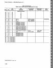
Tabte
7-23
ROM
Bank
Selection
Data
Bank
DO
cE0-7
ROM
0
1
2
3
4
5
6
7
I
9
10
11
12
13
14
15
0
1
o
1
0
1
0
1
0
1
0
1
0
1
0
1
0
0
1
1
2
2
3
3
4
4
5
5
6
6
7
7
454U3060
454U3060
456U1010
456U1010
456Ur020
456U1020
456U1025
456U1025
456U1035
As6Ul
035
456U301
5
A56U301
5
456U3020
456U3020
A56U3030
456U3030
GPIB
Swltches.
At address
7C00,
buffe r u2O4E
writes
the
rear-panel
GplB
switch
data
onto
the
data
bus.
.A.resistor-capacitor
combination
decouples
each
switch
line
to minimize
noise
and
unwanted
pulses
picked
up on
the
long
circuit
board
lines
to
th6 rear
panel.
GPIA.
Generat
purpose
Interface
Adapter
(GplA)
U2050
translates
microprocessor
commands
on
the
microcomputer
bus
into
appropriate
codEs
and
protocol
for
the GPIB
bus. lt
also
decodes
data
from
the
GplB
for
the
microcomputer
bus._ lnterrupts
are
generated
by
pulling
down
on
the
GptB
SRe
line.
fne
Cnf
CLK
tini
provides
the
clock
reference.
This
lC
is
accessed
at
address
7A00.
The
GPIB
Interface
board (A30A57)
connects
the
r€ar-panel
IEEE
488
PORT
(GptB
connector)
to
the
G.PIB.
board,
through
the GptB
Extender
UoarO
(nSOet;.
The
interface
board
contains
two octal
transceiveri,
Ul011 and
U1012,
that
transfer
GptB
data
between
the
rear-panel
connector
and
the
GplA circuit.
7-97