


o
o
o
o
o
o
o
o
o
o
a
o
o
o
o
o
a
o
a
o
o
o
o
o
o
o
o
o
o
O
o
a
I
o
a
o
O
a
o
o
a
a
?
O
change
in
input
power
frequency
or
power
supply
vol-
tage and
notifies
the
microcomputer.'
en
etapiid
time
meter
is
also
located
on
the
board
to
give
a
indication
of
total instrument
operating
time.
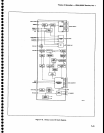
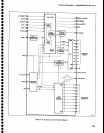
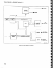
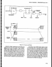
RF
lhterface
Circuits
The
RF
interface
includes
the
digital
control
circuits
that receive
the addr€ss
and
instruition
data
from
the
microcomputer
and
decode
it
to control
the
RF
Attenua-
tor, Transfer
Switch,
and
lF
selection.
The
power
sup-
plies
.
that
are
required
to
drive
the
att€nuator
and
switches
are
also
includ€d.
Address
decoder
U2045
latches
the
data
at
the
input
of
U3O46
whenever
the
microcomputer
selects
address
4F.
Table
7-7
lists
the purpose'of
each
data
line
from
the
buffer.
Theory
of
Opera{on
-
494Ll4g4Ap
Servtce,
Vot.
1
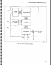
the
unblanking
gates,
which
furnish
cuffent
to
the
Z_
Axis
drive
amplifier
to drive
the crt
control
grid.
The
Z-Axis
Drive
Amplifier
is
an
operational
amplifier
that consists
of
transistors
e3047,
e4125,
and
04065.
and
retated
components.
R1OS0
is
the
input
resistance
for
the amplifier,
and
R2066
is
the
feedback
lej;is-tor.
The
output
is
ctamped
by
diodes
CR3059
and
CR3066
to
protect
the amptifier
from
transient
surges
in
case
of crt
arcing.
The
amplifier
is
driven
Oy
two
sources,
exclusive
of each
other;
U203gBpzA42-drives
llt_e^^Tplifi€r
during
readout
disptay
periods,
and
U2038A|O2O44
drives_
the
amptifier'
during
sweep
display
periods.
U2039
is an
AND-NOR
gate
that
pro_
vides_th€
logic
to one
input
of
NAND
gaie
U2O38A
to
turn
Q2044 on
or off.
The
R/O
OFF
line
and
the output
of
U2039 must
both
be high
for
U203gA
to fumish
current
to
Q2044.
Table
7€
lists
th€ conditions
under
which
U2039
wiff
output
a
high
to U2oggA.
Table
7-7
RF
INTERFACE
LINES
Table
7-8
U2039
TRUTH
TABLE
o1
Q2
o3
Q4
o5
Q6
o7
Purpose
Enables
10
dB
attenuator
No
connection
Enables
30
dB
attenuator
baseli
Enables
current
drivers
e2O2S
and
e302g
Enables
transfer
switch
driver
9.:1.""F _829
MHz
tF (high
state)
or
2022
MHz
lF (tow
state)
Enables
20
dB attenuator
U3046
output
(line
Q8)
CLIP
Z-Axis
Blank
Storage
Ofi
SWP
GATE
Gonditlon
000111000
When
Q4 of
U3046
goes
tow,
e2025
and
e302g
conduct.
This
raises
the Vcc
of
attenuator
drivers
U3034,
U3029,
and
U30Og
to +16V
for
approximatety
100
ms to
energize
the
attenuator
solenoi'ds.
A
diode
protects
each
attenuator
driver
output
line
lrom
the
inductive
voltage
surge
that
occurs
when
the solenoids
change
stat€.
The
Transfer
Switch
operation
depends
on
the out_
put
of
O302S/O9024.
The
e5
ouiput
of
U3046
is
applied
to
the input
of
operational
amptifier
U4O2g,
which
drives
differentiat
amptifier
O2025/O3O24.
When
Q5
goes
high,
Q3025
is
biased
on
and
the
Transfer
Switch
selects
the external
mixer.
When
e5
goes
low,
Q3024 is
bias€d
on,
and
the
internat
mixer
is
selected.
Diodes
CR3018
and
CR3017
protect
the
transistors
from
voltage
spikes
induced
when
the
Transfer
Switch
changes
state.
Z-Axis
Circuits
The
Z-Axis
circuits provide
the
drive
currents
and
bias voltage
to
operate
the crt.
They
consist
of
the
intensity
control
logic
cireuits,
which
control
the
crt
bearn current
for
normal
signat
display
operations,
and
Only
the combinations
shown
in
Table
7-g
plus
a
high on
the RIO
OFF
tine
wiil
gate
a
tow out
of
U203gA.
When
the
U2038A
output
is
low, emitter
current
is
fur-
nished
to
Q2044, which
in
turn furnishes
current
through
R2051
(the
input
resistance
of
the Z-Axis
drive
amplifier)
to Q3047.
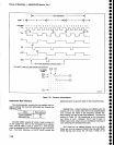
U20g4B
is
a single-shot
muttivibra-
tor
that
produces
a
3
micros
pulse
to
blank
the crt
beam
during
trace return,
between
readout
and
signal
display.
The
other
source
of
input
current
to
the Z-Axis
drive
amplifier
is
Q2042.
This
transistor
is
turned on
by
U20388
when
R/O
UNBLANK
is
high and
R/O
OFF ia
low.
Ql028
is
the
current
source
for
divider
Rl030iR1025
that
establishes
the operating
point
for
0.2042
and
Q2044,
which
s€ts
the intensity level.
Diodes
CR1045 and
CR1
043, connected
from
the base
ot
Q2042 and
Q2044
to the emitter
ot
eZ02Z,
timit
the
dtsplay intensity.
These
diodes
prevent
the
bases
from
going
more
positive
than
approximatety
0.6 v above
the
emitter voltage
of
Q2022.
This circuit,
which includes
lnt
Limit
adjustment
Rl027, sets
the maximum
current
for
both
Q2042
and
Q2055.
011
111
100
110
0
1
0
0
0
0
1
0
1
000
111
001
10r
000
7-49