


Performance
Check
procedure
_
4g4Ll4g4Ap
Servlce
Vol.
1
o
o
a
o
o
o
O
o
o
a
o
I
o
o
o
I
o
I
o
o
)
I
o
o
I
o
a
o
a
I
I
a
a
o
t
t
a
a
o
a
a
a
o
o
o.
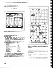
Check
that
the
difference
between
the
SAVE
A
and
V|EW
B_disptays
is
tess
than
O.S
dB
up
to 1.g
GHz,
less
than 1.5
dB from
.t.g
GHz
to
1g
GHz,
and
tess
than
3.0
dB
from
18
GHZ
to
21
GHz.
Make
a
note
of
the
level
difference
between
the
SAVE
A
and
VIEW
B
displays.
p.
To
check
the
next
10
dB step,
reset
the
genera_
!o^r lor
a
0 dB
power
meter
reading,
and
replace
the
20
dB attenuator
with
a 10
dB
attenuitor.
_ - _e. I"peat
parts
m
through
o,
except
that
the
next
MfN
RF AfiEN
dB setting
witt
Ue 20
and
rhe
reference
levelwill
be
-10
dB
flabte
4-5).
.
r.
lepeat,the
procedure
for
the
third
10
dB
step
lfing__T19le-4-5
as
a
guide
for setup
information
for
th€
third MIN
RF
ATTEN
dB setting.
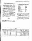
PART
II
a.
The
30-60
dB
range
is checked
in
the same
fashion
as
the
0-30
dB
range
using
different
power
levels
because
of
the
output
level
limitition
of
the
signal
generator.
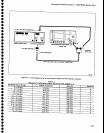
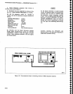
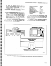
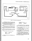
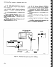
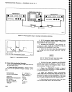
b.
Connect
the
test
equiprnent
as
shown
in
Figure
4-14.
Set
th€
Spectrum
Analyzer
controls
as
follows:
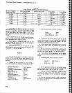
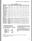
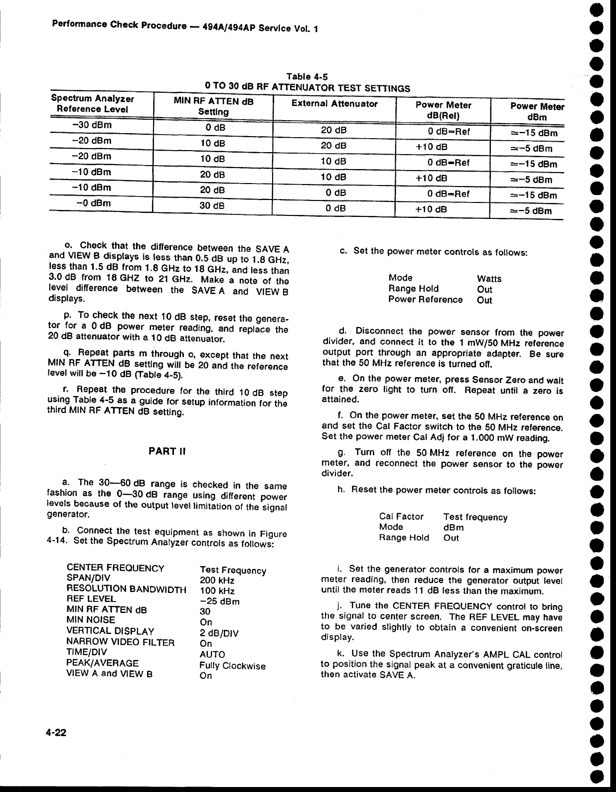
Tabte
4-5
O TO
30
dB RF
ATTENUATOR
TEST
SETTINGS
Test
Frequency
200
kHz
100
kHz
-25
dBm
30
On
2
dB/Dtv
On
AUTO
Fully
Clockwise
On
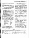
c. Set
the
power
meter
controls
as
follows:
Mode
Watts
Range
Hold
Out
Power
Reference
Out
d.
Disconnect
the
power
s€nsor
from
th€
power
divider,
and
connect
it to
the 1
mW/S0
MHz reference
output
port
through
an appropriate
adapter.
Be
sure
that
the 50 MHz
reference
is
turned off.
e. On
the
power
meter,
press
SensorZero
and
wait
for
the
zero
light
to
turn
off.
Repeat
until a zero
is
attained.
f. On
the
power
meter,
set
the
S0 MHz
reference
on
and
set
the
Cal Factor
switch
to
the
S0 MHz reference.
Set
the
power
meter
Cat
Adj
for
a
1.000
mW
reading.
g.
Turn
off
the
50
MHz
reference
on the
power
meter,
and
reconnect
the
power
sensor
to the
power
divider.
h.
Reset
the
power
meter
controls
as follows:
Cal
Factor
Test
frequency
Mode
dBm
Range
Hold
Out
i. Set
the
generator
controls
for
a maximum
power
meter reading,
then reduce
the
generator
output tevel
until
the
meter
reads
't
1
dB less
than
the
maximum.
j.
Tune
the
CENTER FREQUENCy
conrrot
to bring
the signal
to center
screen.
The
REF
LEVEL may
have
to
be
varied
slightly
to
obtain
a convenient
on-screen
display.
k.
Use
the
Spectrum Analyzer's
AMPL
CAL
control
to
position
the signal
peak
at a convenient
graticule
line,
then activate
sAvE
A.
CENTER
FREQUENCY
sPAN/DtV
RESOLUTION
BANDWIDTH
REF
LEVEL
MIN RF
ATTEN
dB
MIN
NOISE
VERTICAL
DISPLAY
NARROW
VIDEO
FILTER
TrME/DtV
PEAK/AVERAGE
VIEW
A
and
VIEW
B
Spectrum
Analyzer
Reference
Level
-30
dBm
MIN
RF
ATTEN
dB
Setting
External
Attenuator
Power
Meter
dB(Rel)
Power
Meter
dBm
0dB
20
dB
0 dB:Ref
--15
dBm
:-5
dBm
--lA;
=-5
dBm
-20
ctBm
-20
dBm
-10
dB,"
-10
clBm
10
dB
20
dB
+10
dB
10
dB
10
dB
0 dB-Ref
20
dB
10
dB
+10
dB
20
dB
0dB
0
dB-Ref :-15
dBm
:-5
dBm
-0
dBm
30
dB
0dB
+10
dB
4-22