


o
a
o
o
a
o
^
r
J
o
I
t
I
o
o
a
o
o
o
o
I
,
o
I
o
t
o
o
o
a
a
a
I
a
I
o
I
I
o
I
t
t
o
I
t
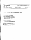
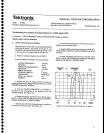
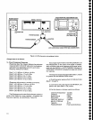
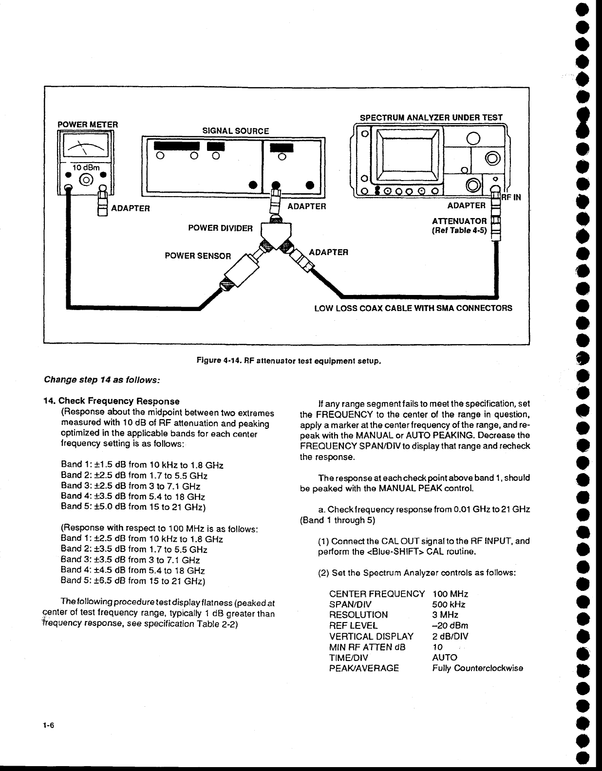
Figure
4.14.
RF attenuator
test
equipment setup,
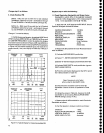
Change
step 14
as follows:
14.
Check Frequency
Response
(Response
about the
midpoint
between
lwo exlremes
measured
with 10
dB of
RF attenuation
and
peaking
optimized
in the
applicable
bands
for each
cenrer
lreguency
setting is
as lollows:
Band
1:
+1
.5 dB
from 10
kHz to 1.8
GHz
Band
2'.
r2.5 dB from
1.71o
5.5
GHz
Band
3:
f2.5 dB from
3
to 7.i
GHz
Band 4:
+3.5
dB from
5.4
to 18 GHz
Band 5:
+5.0
dB from
15 to
21 GHz)
(Response
with respect
to 1OO
MHz
is as
follows:
Band
1
:
.t2.5
dB from
I
O
kHz
to
1
.8 GHz
Band
2:
+3.5
dB
from
1.7
to 5.5
GHz
Band 3:13.5
dB from
3
to
7.1
GHz
Band 4:14.5
dB from
5.4
to 18
GHz
Band
5:
+6.5
dB
from
't5
to 21 GHz)
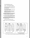
The
folfowing
procedure
test display
flatness
(peaked
at
center
of test frequency
range,
typically
1 dB
greater
than
Trequency
response,
see
specification
Table
2-2)
lf any range
segment
f
ails
to
meet the
specif
ication,
set
the FREOUENCY to
the
center
of
the
range in
question,
apply a
marker
at the center f requency of
the range, and re-
peak
with
the MANUAL
or
AUTO
PEAKING.
Decrease
lhe
FREOUENCY SPAN/DlV
to display that
range
and
recheck
the
response.
The response at each check
point
above band 1
,
should
be
peaked
with
the MANUAL
PEAK
control.
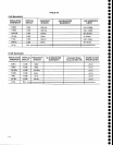
a. Checklrequency
responsefrom
0.01
GHzto 21 GHz
(Band
1
through
5)
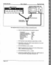
{1)
Connecl
the
CAL
OUT signal
to the RF
INPUT,
and
perform
the <Blue-SHIFT> CAL routine.
(2)
Set
the
Spectrum
Analyzer controls
as
lollows:
CENTER FREOUENCY
100MHz
SPAN/DIV 500 kHz
RESOLUTION 3
MHz
REFLEVEL
-20d9m
VERTICAL
DISPLAY 2
dB/DIV
MIN
RF
ATTEN
dB 10
TIME/DIV
AUTO
SPECTRUM
ANALYZER UNDER TEST
POWER METER
SIGNAL
SOURCE
ADAPTEF
ADAPTER
POWEB
DIVIDEB
POWER
SENSOR
ADAPTEF
LOW LOSS COAX CABLE
WITH SMA CONNECTORS
1-6
PEA}VAVERAGE Fully
Counterclockwise