


I
o
a
o
o
a
o
o
o
o
o
)
o
o
o
a
a
I
t
I
I
o
o
t
o
o
I
o
I
o
o
o
o
e
o
o
I
o
o
o
o
a
o
o
Theory
of
Operation
-
4g4ful4g4Ap
Service,
Vot.
1
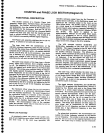
100 MHz
reference
signal
from
th€
grd
Converter,
is
divided
down
to
25
MHz, on
the
Synthesizer
board,
and
applied
as
the
reference
signal
to the
mixer
on
the
Offset Mixer
board.
The 25
MHz
signal
is
also
applied
as
a
clock
signal
to
+N
counter
circuits,
on
the
'Syn-
thesizer
board,
which output
a frequency
(depending
on
the
+N
number
from
th€
processor)
tieiween
g2lHz
and
94 kHz.
This
signat
is
apptiect
to
the
phase/frequency
detector
on
the
Offset
Mixer
board.
where
it
is
compar€d
to
tho lF
output (difierence
between
th€
25
MHz
reference
and
the autput
trom
the
VCO
(voltage
controlled
oscillator)
and
any
difierence
is
output
as an
€rror
voltage
to
the Enor
Amplifier.
The
VCO
operates
between
25.032
MHz
and
25.094
MHz,
depending
on
th€
driv€
from
the
Error
Amplifier.
This
signal
is
apptied
to thg
RF input
of
the
mixer
on
th€
Offset
Mixer
board,
where
it
mixes
with
the
25 MHz
reference
frequency.
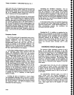
The
difference
fre-
quency,
which
is
between
32kHz
and
94 kHz,
is
applied
t1 thj
phase/frequency
detector
and
compared
to the
+N
frequency.
lf
the
two
signals
are
edge
and
fre_
qugngy
coincident,
phase
lock occurs.
lf
they
do not
coincide,
an
error
signal
is
generated,
passed
through
the Error
Amplifier,
and
apptied
to
the VCO
to
shift
the
oscillator
frequency
until
it
is
phase
locked.
This
evolu-
tion
typically
lasts
for
only
a few
milliseconds,
so
the
inner
loop
phase
lock
is
essentially
instantaneous.
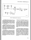
The_ outer
loop,
which
includes
the inner loop
cir-
cuits (Offset
Mixer,
Error
Amplifier,
and
VCO) consists
of
the
Strobe
Driver,
phase
GatE,
Error
Amplifier,
and
1st
LO.
(fhe
Harmonic
Mixer,
Auxiliary
Synthesizer,
and
Counter,
are
a
part
of
the operation,
but
are
not
considered
a
part
of
the
foop.)
The signal
between
2S.0gZ
MHz
and
25.094
MHz
from
the VCO
is
applied
to
the Strobe
Driver where
it is
divided
by five,
filtered,
and sent
to the
phase
Gate
Detector
as
a
strobe
signal
between
5.006
MHz
and
5.01
9
MHz.
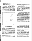
This
strobe generates
line
spectra
that
are
egually
spaced
approximately
S
MHz
over
the spec-
trum.
At about
the 400th
line, which
corresponds
to
2
GHz, assuming
that
the l st
LO is
tuned to
a fre-
quency
near
2
GHz, one
of
these
lines
(at
about
the
400th
line)
will
be within
2.5MHz of
the 1st LO fre-
quency.
The
Phase
Gate
Detector will
then
output
an
enor
signal
that
is
proportional
to
the dilference
between
the lst
LO frequency
and
that of
the
nearest
strobe
line,
if
that
difference
frequency
is
less
than
approximately
1 MHz.
For
phase-lock
acquisition,
the microcomputer
cal-
culates
the strobe
frequency
required
for
the desired
l
st
LO frequency.
The
strobe is
set
to
this
lrequency
and
the
lst
LO
is
set
to
the required
harmonic of
the
strobe.
The
outer
loop
is
closed,
and
the
microcom-
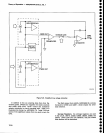
couNTER
and
PHASE
LocK
sEciloN
(Diagram
g)
FUNCTIONAL
DESCRI
PTION
This
section
consists
of
a
Counter,
phase
Lock
assembly,
phase
Gate,
Harmonic
Mixer,
and
Auxiliary
Synthesizer.
The
Counter,
Harmonic
Mixer,
and
Auxili-
ary
Synthesizer,
form
the
nucleus
of
the frequency
con-
trol
hardware
for
the instrument.
Both
the
lst
LO and
2nd
LO frequencies
are
controlled
via
a
firmware
based
control
loop
that
uses
data
from
the
Counter
as
feed-
back
to control
oscillator
frequency.
The
10
MHz
lF
is
also
counted
to accurately
calculate
signal
frequency.
The
phase
Lock
assembly
stabilizes
the
t st
LO
fre-
guency.
lt
consists
of
an
outer
and
inner
loop.
_ --l!g-
inner
loop
uses
the subharmonic
of
the
100
MHz
reference
frequency,
from
the
3rd
Converter,
to mix
with
the output
from
a
2i.Og2to
25.095
VCO
and
compares
this lF
difference
with
a
+N
number
(between
32 kHz
3nd
94 kHz)
set
by
the
processor.
Any
devia-
tion is
detected
by
a
phase/frequency
detector
whose
output
enor
voltage
is
used
to
pull
the VCO
frequency
and
phase
into
lock
with
the
inner
loop
reference.
_ .
The
_outer
toop
consists
of
the
inner
loop,
a
Strob€
Driver,
Phase
Gate Detector,
Error
Amplifier,
and
th€
1st
LO.
The
frequency
of
the inner
loop
VCO
is
divided
down and
applied
as
a
strobe
putse
to
the
phase
Gate
Detector.
This
strobe.pulse
contains
energy
at frequen-
cies
equally
spaced
throughout
the
specirum.
One
of
these frequencies
wiil
be
within
2.5
Mi{z
of
th€ l st
LO
lrequency
at
the other
input
to
the
phase
Gate
Detector.
The
Phase
Gate
Detector
outputs
an
error
signal
pro-
portional
to
the
difference
between
the nearest
strobe
and
th€
lst
LO
frequency.
This
error
signal
is amplified
and
filtered
by
the
Error
Amplifier
and
aiptieO
to the
FM
coil
of
the
1st
LO
to
pull
it
into
trequency
and
phase
lock
with
th€ strobe.
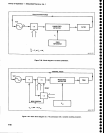
The
Harmonic
Mixer
mixes
the
1st
LO
freguency
and
a harmonic
of a
synthesize
d
200-2ZA
MHz
'signal
from
the.
Auxiliary
Synthesizer.
The
exact
frequency
of
the synthesizer
signal
is
a
function
of
the
+N
factor
from
the
processor.
The
Harmonic
Mixer
output
is a
signal
within
the
10
to
g0
MHz
range.
This
signat
is
divided
in
the
Auxitiary
Synthesizei
and
sent
to the
Counter.
The
microcomputer
looks
at
the resultant
count
and
decides
which
way
to
move
the 1st
LO
to
bring it
to ths
correct
frequency.
Phase
Lock
Assembly
.
As
previously
stated,
the
phase
lock
system
con_
sists
of
two frequency
servo
loops,
called
the outer
loop
and
inn€r
loop.
In
the
inner
loop
operation,
the
7-77