o
o
o
O
o
o
t
o
o
t
o
I
o
O
o
o
o
I
o
o
O
o
o
a
o
a
o
o
I
O
I
o
I
o
o
I
I
o
o
O
o
o
o
I
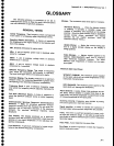
Sensitvity.
Measure
oJ
a.
spectrurn
analyzef
s
ability
to
display
minimum
rever
signars,
"*pi".J"o
in
vorts
or
decibets.
Intermediate.
tr"qu"n"V
-ifei
bandwidth,
display
mode,
and
any
other
innueniinji"'.to*
must
be
given.
Spu.rious
Response.
_.
A
respons€
of
a
spectrum
analyzer
whErein
the
displayed'frequency
is
not
related
to
the
input
frequency.
Hum
Sidebands.
Undesired
responses
cr€ated
within
the
spectrum
analyzer,
"pp"urlng
on
the
display,
that
are
separated
trom
the
desired
response
by
the
fundamental
or
harmonic
of
the
power
line
frequency.
Noise
Sldebands.
Undesired
response
caused
by
noise
internal
to the
spectrurn
analyzer
appearing
on
the
display
around
a
desired
,".ponr".
Resldual
Response.
A
spurious
response
in
the
absence.of
an
input
signal.
(Noise
und:
r.ro
pip
are
excluded.)
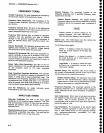
DIGITAL
STORAGE
TERMS
Digitatfy
Stored
Disptay-
A.disptay
method
whereby
the
displayed
function
is
held_.in'a'digital
memory.
tne
display
is
generated
by reading
the
dita
ouf
ot
mernory.
Digltally-
Averaged
Display.
A
disptay
of
the
average
value
of
digitized
data
computed
by combining
serial
samples.
Multiple
Disptay
Memory.
A
digitaily
stored
disptay
hav,
in_g_
multiple
memory
sections
wtrictr
""n
b"
displayed
separately
or
simultaneously.
Clear (Erase).
presets
memory
to
a
prescribed
state,
usually
that
denoting
zero.
Save.
A
function
which.
inhibits
storage
update,
saving
existing
data
in
a
section
of
a
multif,le
,i"rory
1".g,,
Save A).
Glossary
_
4g4Al4g4Ap
Service,
Vol.
1
View
(Display).
Enables
viewing
of
contents
of
the
chosenmemory
section
(e.g.,
'.Vidw
A,
displays
the con-
tents
of
memory
A;
',View
B"
displays
the
contents
of
memory
B).
Max
Hold (peak
Mode),
Digitally
stored
display
mode
which,
at each
frequency
addresi,
compares
thsincom-
ing
signal
level
to
the stored
level
and
retains
the
greater.
ln
this
mode,
the
display
indicates
the
peak
lev€l
at
each
frequency
after
-
several
successive
sweeps.
Scan
Address.
A number
representing
each
horizontal
data
position
increment
on
a
direited
Ueam
type
display.
An address
in
a
memory
is
associated
with
each
scan
address.
Volatile/Non-volatile
Storage.
A volatile
storage
system
is
one
where
any
total loss
of
power
to the
system
will
result
in
a
loss
of
stored
information.
Non-volatite
I"Tory
is
not
subject
to the
instrument
power
supply
for
its
storage.
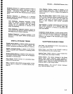
WAVEFORM
MARKER
TERMS
Live
Trace.
Any
combination
of
the
A
trace
and/or
the
B
trace
when
SAVE
A
is off.
Active
Trace.
Live Trace
or
the
B-SAVE
A
trace (a
trace
recalled
into
B is
not
an active
trace).
Inactive
Trace.
SAVE
A
trace
or
a
trace
recalled
into
the
B
display
before
the
sweep
is started.
Primary
Marker.
The
marker
displayed
in
the
Single
Marker
mode
whose
frequency
and/or position
is
gllseo
when
tuning
with
the
CENTER/MARKER
FRE_
QUENCY
control.
When
two
markers
are
displayed,
the
brightest
marker
is
the
primary
marker.
Secondary
Marker.
The
"second,,
marker;
displayed
only
in
the Delta
Marker
mode.
A-3


