


o
o
o
o
o
o
o
o
o
o
o
o
o
o
a
o
o
o
o
o
o
o
o
o
o
o
o
o
o
o
o
o
o
o
o
o
o
O
o
o
o
a
o
o
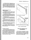
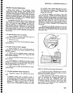
Four
Cavlty
Fllter-The
characteristics
of
the
filter
are checked
with
a
network
analyzer.
Freguency
of
the
filter
is
2A72MHz,
bandpass,
t-S
Ul-lz
down,
is
1
dB,
return
loss
is
20
dB
or
greater,
and
insertion
loss
is
1
clB. lf
the
seal
is
broken
on
any
tuning
slug,
adjust
for
maximum
return
loss.
Malntenance
-
494A/494Ap
Service
Vol.
1
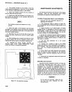
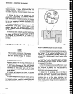
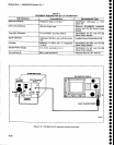
Mlxer*To
gain
access
to the
Bias
adjustments,
rernove
the
assembly
from
its
mounting;
then
remove
the
mounting ptate
on
the
bottom
of
the
assembly.
Reconnect
the Mixer
to
the input/output
lines,
using
the
same
cables
(cable
length
of
semi
rigid
cables
is iriti_
cal).
Appty
the
CAL
OUT signat
to
the RF
INpUT
and
tune
a rnarker
to center
scr€en,
Simultaneously
adjust
99th
bjas
porentiometers,
R1021
and
R1022,
liee
Figure
6-11)
for
maximum
signal
amplitude.
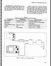
Table
6-6
EOUIPMENT
REQUIRED
FOR
RETURN
LOSS
ADJUSTMENT
Test
Equlpment
Recommended
Type
Spectrum
Analyzer
TEKTRONIX
49X-Series
or 7L14
Signal
Generator
TEKTRONIX
SG
503 for
the TM
S0O-Series
VSWR
Bridge
Wiltron
628F50
10
dB
& 1
dB
Step
Attenuators
Hewlett
Packard
355C
&
g55D
Termination
Tektronix
Part
No.
011-0049-01
Adapter
Tektronix
Part
No.
175-0419-00
Tll
50O M.ine
F.rme
Test
fg0-S€ries
Spoctrum
Anatyz€r
a{te76
Frequency
range
)110
MHz
+10
dBm
at
110
MHz
50O,
0 dB
to 40
dB
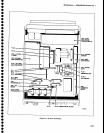
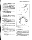
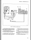
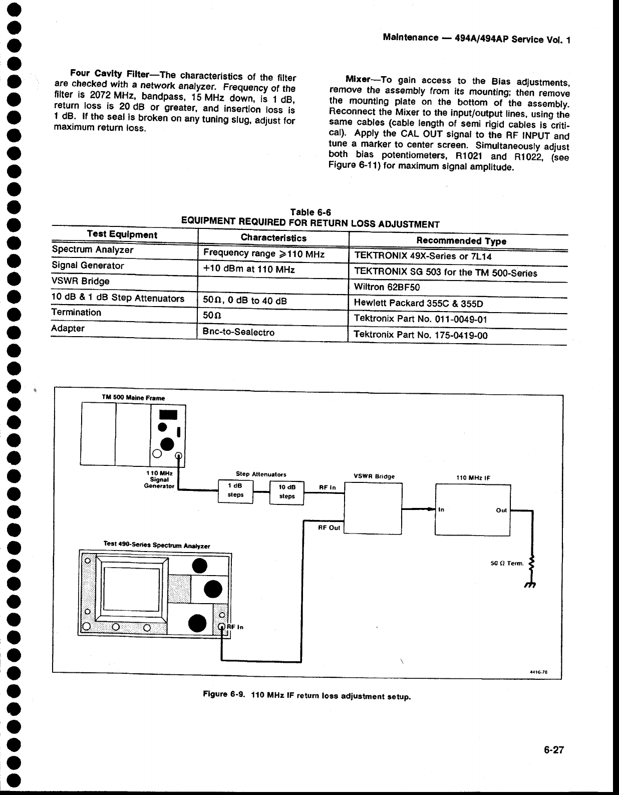
Figure
6-9.
110
MHz lF
return
loss
adjustment
setup,
6-27