


o
o
o
o
o
a
a
I
o
o
o
o
a
o
a
O
a
o
a
a
o
o
o
o
a
o
o
o
O
o
O
o
o
o
o
a
o
o
o
o
o
o
a
o
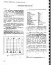
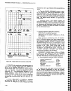
wrTlt
F|RST
stOilAL
ATC€NTER,
SEOol{D
CAil
EE Wrn$t
TH|S
RAI{OE
r|
_ta
-tt
-tl
{l
-€
€
4'
{
{l
5s6035
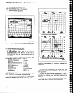
Figure
4-4.
Cenler
frequency
drift with
the 1st
LO
tocked.
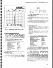
5. Check
Center
Frequency
Stabilitv
lplrl
i.f
50
Hzlmin'or
r".J
*itii-'irt
Lo
tocked
(SPAN/D|V<200
kHz
for
band
1
and
bands
5
through
12,
and
SPAN/D|V<I0O
kHz
for
bands
2
through
4) after
t hour
of
warmup
time
in
a
stable
ambient
temperature).
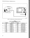
a.
Appty
the
Catibrator
signalto
the
RF tNpUT.
b.
Set the
Spectrum
Analyzer
controls
as
follows:
CENTER
FREQUENCY
1OO
MHz
SPAN/DIV
S0
Hz
AUTO
RESOLN
ON
REF
LEVEL
-15
dBm
MIN
RF
ATTEN
dB
O
VERTICAL
DTSPLAY
2
dB/Dlv
TRIGGERING
FREE
RUN
V|EW
A and
V|EW
B
On
TIME/DIV
AUTO
READY
light
to
go
out.
d. After
the
READY
light
is
out,
activate
SAVE
A.
e.
Activate
the NABROW
VTDEO
FILTER.
When
the
NARROW
VIDEO
FILTER
is
acivated,
the
AUTO
sweep
mode
slows
the sweep
to
10
s/div.
Performance
Check
procedure
-
4g4A/4g4Ap
Service
Vol.
1
WhCN
thE
NARROW
VIDEO
FILTER
iS
acivated,
the
UNCAL
light
will
come
on.
The
light
should
be ignored
for
purposes
of
this
check.
f. Press
SINGLE
SWEEP
again
and
wait
for
the
READY
light
to
go
out.
g.
Note
the
disptacement
between
the
SAVE
A
peak
and
the VIEW
B
peak.
This
is
a
measure
of
the
fre-
quency
drift.
h.
check
that
displacement
of
the
vtEw
B
peak
is
no
more
than
1 division
in
the
positive
direction,
or
0.72
division
in
the
negative
direction.
See Figure
4-4.
6.
Check
Residuat
FM
{Witnin
7N kHz
over
20
ms
with
the
i
st
LO
unlocked
(SPAN/D|V>200
kHz
for
band
1 and
bands
s
through
12
and
SPANIDfV>10OkHz
for
bands
2
through
4.))
{Within
(10
+
2N)Hz over
20 ms
with
the 1st
LO
locked
(SPAN/D|V<200
kHz
for
band
1
and
bands
5
through
12 and
SPAN/D|V<IO0
kHz
for
bands
2
through
4.)l
a.
Apply
the Catibrator
signatto
the
RF
tNpUT.
b.
Set
the
Spectrum
Analyzer
controls
as follows:
CENTER
FREOUENCY
100
MHz
SPAN/DIV
1 MHz
RESOLUTION
BANDWTDTH
100 kHz
VERTICAL
DTSPLAY
2
dB/DtV
MIN
RF
ATTEN
dB
O
REF
LEVEL
TIME/DtV
TRIGGERING
VIEW
A and
VIEW B
-23
dBm
20 ms
FREE
RUN
On
c.
Disable
the
1st LO synthesis
and
phase
lock
by
pressing
<Blue-SHIFT>
10
dB/DlV.
A message
"FRE-
OUENCY
CORRECTIONS
DTSABLED:
USE
HELp,.wiil
be displayed
on the
CBT.
cl.
Reset
the SPAN/DIV
to
100 kHz, and recenter
the
100
MHz calibrator
signal
on
screen
with
the
CENTER
FREOUENCY
controt.
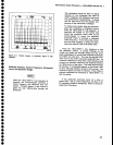
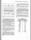
E.
SEt
thE VERTICAL
DISPLAY
tO LIN. POSitiON
thE
signal so
the slope (horizontal
versus
vertical
excursion)
of
the response
can
be determined
as
illustrated in
Fig-
ure 4-5A.
Slope
determination
may
be made easier
by
switching
VIEW
B off, and
using
SINGLE
SWEEp
and
SAVE
A
to freeze
the display
at a
convenient
position
on
the
graticule.
The
slope
should
calculate
to
approxi-
mat€ly
1
0 kHzldivision.
4-9