


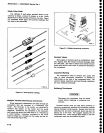
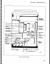
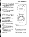
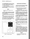
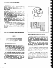

Fan
brackets
should
be
installed
as
in Fig-
ure
6-8.
7.
Insert
the
posts
of
the
brackets
into
the holes
provided
in
the resilient
mount
and
install
the remaining
bracket, with
lockwashers
and
nuts,
to
the
back
side
of
the
power
supply
housing.
8. Reconnect
the
fan
to the Fan
Drive
board
then
replace
the cover,
with
the fan, onto
the
power
supply
module.
9. After
installing
the
six
screws
that hotd
the
cover
in
place,
ensure
that
the
fan
assembly
moves
freely.
Replace
the coaxial
cable
in
the
plastic
retaining
clip.
10.
Reinstall
the
Power
Supply
assembly
as
directed
under Power
Supply
Replacement.
Apply
power
and
check
for
normal
fan
operation.
Maintenance
-
494A1494Ap
Servlce
Vol.
I
4.
The
resilient
mounts
at
the
corners
of
the fan
frame
should
be
replaced
if a
new
fan
is
to
be
installed
or fan vibration
is
generating
spurs
on
the
display.
5. Insert
four
resilient
mounts
into
the
corners
of
th€ fan, flush
with
the
fan
frame.
6. Install one
ol
the
fan
brackets
to
the
power
sup-
ply
housing
by
attaching
its
lock
washers
and
nuts
to
th€
back
of
the housing.
MAINTENANCE
ADJUSTMENTS
The
following
procedures
are
not
part
of
the regular
calibration.
They are only
performed
when
certain
assemblies
are
replaced
or
after major
repair.
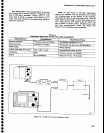
110 MHz
lF
Assembly
Return Loss
Calibration
Table
6-6
lists
test
equipment
required
for
adjusting this assembly.
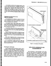
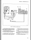
1. Test equipment
setup is shown
in
Flgure
6-9.
The lF
assembly
must
be
removsd
to
gain
access
to the
adiustments.
2.
Apply
110 MHz at
2V
peak-to-peak
(+10
dBm)
through 35 dB of attenuation
to
the
RF
Input
of
the
vswR
bridge.
connect the RF out of
the
vswR
bridge
to
the
RF Input of
the
spectrum analyzer. (Do
not
con-
nect
the 110 MHz
lF
to
the vswR
bridge.)
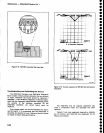
3. Set
the
test
spectrum
analyzer Center Frequency
to
110
MHz,
Frequency
Span/Div to 5 MHz, REsolution
Bandwidth
to 3 MHz, Vertical Display
to 10
dB/Div, and
Ref Levelto
-20
dBm.
4, Set the step attenuator for a
full screen
(-20
dBm) display.
5. Connect the 110MHz lF input
to the
vswR
bridge
and connect a
50O
termination to the
output of
the lF amplifier. Now
plug
the
power
cable
P3045
into
the + and
-15
V source and
ground
the
case
of
the
assembly.
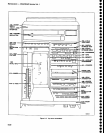
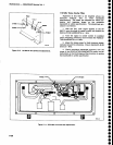
6.
Adjust
C2047
and
Cl054
(Figure
6-10) simultane-
ously
for
minimuh signal
amplitude
on
the
spectrum
analyzer
display.
Minimum
amplitude must
be
at
least
-55
dBm.
7. Disconnect
te6t
equipment setup and replace
the
110 MHz
lF
assembly.
2072MHz
2nd Converter
The
2nd
Converter assembly
consists of a four cav-
ity
2072
MHz
band-pass filter,
mixer, and a 110
MHz
low-pass filter. The assembly is
precalibrated prior
to
installation, and
requires no
calibration after
it
is
installed. We recommend
replacing the
assembly
if
it
should
malfunction. The following
procedures
describe
adjustments
that can be made
if
the biasing
should mal-
function
or
the seal on any
of
the
filter
tuning slugs
is
broken.
The
mixer diodes are
not
to be
replaced in
the
field.
Return the
assembly
to
Tektronix, lnc., for repair.
Do
not open
the assembly. Adjust the tun-
ing
slug only after
checking the
filter
characteristics.
o
o
o
o
a
o
o
o
o
o
o
o
o
o
o
O
o
o
o
o
o
o
o
o
o
o
o
o
o
o
o
o
o
o
O
o
o
O
O
o
o
o
o
o
6-26
Flgure
5{.
Fan
assembty
mounting.