


Theory
of
Operatlon
-
4g4A/4g4Ap
Service, Vol.
1
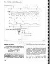
Sweep
Holdofr
During
retrac€,
the
sweep
must
b€
held
off long
enough
for
the timing
capacitors
in the
integrator
to
discharge
and
the circuit
to
stabilize.
To
prevent
flicker,
the holdotf
period
must
vary
as sweep
tim€
changes.
U30258 and
three
timing
capacitors (C3027,
C3030, Lnd
C3032)
plus
a resistor (R3030)
form
the
hotdoff
circuit.
During
sweep
time
pin
5
of
U1017A is
high.
This
pulls
pin
6 low
and
discharges
Cg0g2. During
retrace,
pin
6
is released
and
the
timing
capacitors
start
to
charge.
When
they
reach
*5
V
comparator
Ug025B
toggles and
its output goes
high.
This, along
with
th€
high
on
pin
13 of
the NAND
gate
U102OD,
provides
the
clock
pulse
for
U2026
to
pass
a
trigger signat
through
to the Sweep
state
controt,
u1025.
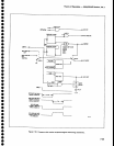
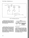
lnterface
Circuits
ln addition
to
the
sweep
circuits,
there are circuits
that interface
between
the
microcomputer
and
the
Reference
Lock
modul€.
These
circuits
generate
an
interrupt
(SER
REO)
when
a change
of
status
in
the
Reference
Lock
modute
occurst
respond
to the POLL
routine, and
provide
data so
the microcomputer
can
monitor the status
of
the Relerence
Lock module.
To
determine
the status
of
the Reference
Lock
module, the
microcomput€r
reads
the
status
of
bits
0
and 1
(DBo
& DBl)
of
the
data
bus
at address
9F.
These
two
bits connect
through
tri-state
buffers
in
u4015C to
th€ |NTL
REF
and
(REF
LOCK)(bar)
tines
from the R€f€rence
Lock
module.
The
INTL
REF
line is
high
when
the internal
rEference
is
used
and low
for
extemal referenc€.
The
{REF
LocK}(bar)
goes
high
when the
3rd LO is
not locked
to
the frequency
refer-
ence
and low
when
it is
locked.
When
address
9F is
read,
U2O1Z
is enabled
and
latches
the
(|NTL
REF)(bar)
and
REF LOCK
signals.
Thus,
the
bits
on
pins
1,2,
and
5,6, of
the
exclusive-nor
gates
in
U2015
match
each
other.
The open-collector
outputs are
wired
together,
so
when
the
outputs
are
high, inverter
U10178
applies
a
low
to the clock
input
of
flip-flop
U2025A.
When
a change
in status
occurs,
one
of the bits
to
the exclusive-nor
gates
(pin
1 or
pin
5)
changes. There
is
now
a difrerence
between
the
present
status and
the
previous
status,
stored
in
U201 7.
One
output
of
U2015
now
switches
low and
a low-to-high
transition
occurs
on
the clock
pin
of
U2025A.
This
triggers
an
interrupt
and
causes
the microcomputer
to
inquire about
the new
status.
Reading
the new status
activates
the latch
and
resets
the
circuit.
Transistor
Q3015,
driven
by
bit D4
at address
1F,
turns
the INTL
REF
(internal
reference)
on
or
off.
The Interrupt and
Service Request
circuit
gensrat€s
the
instrument
bus interrupts
and responds
to
the sub-
s€quent
poll
routine from the
microcomputer.
There
are
two
sources of
an interrupt
from
the sweep
board,
either an
EOS
(end-of-
sweep)
has occurr€d
or
a
change
of status
of
the
reference
lock
module
is
detect€d. When
an EOS
occurs, and
provlded
the EOS
Interrupt
Enable bit is high,
the flip-flop
U1010A is
clocked
and
its Q(bar)
goes
low.
This
produces
a
high
out of
u1020B
which
turns
Q4032
on
to
pullthe
instru-
ment
bus
line
SER REQ
(servic€
request)
low
and
forces an interrupt.
The microcomputer response
to
an interrupt
is
with
a
poll
routine, lt first writes
FF
to the instrument
address
bus.
The Sweep
board
address
decoders
nor-
mally
r€spond
only
to
addresses
0F,
lF,
and
9F, but
the
interrupt
circuit detects when
bit
7
of
the address
bus
(AB7) goes
high.
The microcomputer
rais€s
the POLL
line and
reads
the
instrument
data bus.
The
output
of
U2010A
goes
low.
This. anded with
the
low out
of
U10104,
generates
a
high
to turn 03020
on
and
pull
bit
DB4 of
the
instrument
bus
low.
When the microcom-
puter
reads a low
on
bit
DB4
it lowers
the
POLL
line
and writes
7F
on
the
instrum€nt
bus.
Again, none
of
the
other
decoders respond. However,
bit
7
(AB7)
of
the
address
is
pulled
low.
The microcomputer now
writes a
word
to the data
bus
with
all
bits
sxcept
bit
DB4
high.
This acknowledges
the
interrupt.
The microcomputor
now
raises
the
POLL line again
and
since
both
inputs
to
U20108
are high,
the output of
the
gate goes
low.
The
POLL line is
then
pulled
low
and
the
low-to-high
transi-
tion clocks
the
low
on
the
D input
of
U10108 through
to
reset
u1010A.
lts
Q
output
then
sets
u10108.
04032
is
cut off,
the
interrupt
is removed, and
the
circuit
is
now ready
for another EOS.
A change-of-status in
the
reference
lock module
causes a low-to-high
transition
on
the clock input of
u2025A
to
latch the
Q
(pin
5)
output high and
the o(bar)
output
low. This
low
is
gated
through U10208 to turn
04032
on, and
pull
SER
REQ
line low. When
the
micro-
computer responds, by
writing FF
and
raising
the
POLL
line,
U2010A
output
goes
low, however,
at
this time
U202OB output
goes
high,
because
of
the
low on
pin
6
of
U2025A. This turns
03025
on and
bit
DB7 on
the
instrument
bus
goes
low. The microcomputer
reads
this
and
pulls
the
POLL
line low. Address 7F
is
written
on
the address bus
and
the POLL
line is raised. This
lorces U2010B to
output
a low and th€ POLL line
again
goes
low
to toggle
U20258.
The
low
Q
output
resets
U2025A to
remove
th€
interrupt or
SER
REQ.
At
the
same
time U2O25B
is reset
and
the
circuit is ready to
repeat
the
sequence.
o
o
a
o
a
o
t
o
o
a
a
o
o
o
o
a
o
o
o
o
o
o
o
a
o
o
o
o
o
I
o
o
o
a
O
o
a
a
o
o
o
o
o
o
7-64